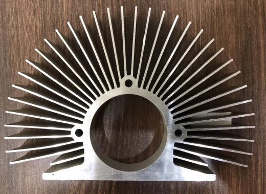
Extruded heat sinks for high-power AI server and GPU cooling
AI accelerator cooling stopped being a conventional heat-sink problem some generations ago. Power per package has roughly doubled twice since the first server-class accelerators, a single GPU board can now carry two or four packages with an HBM stack beside each die, and the voltage regulator adds its own losses. The part our customers ask us to extrude is no longer a finned block with a fan in front of it. It is either a high-aspect-ratio fin stack, a heat spreader that has to move heat sideways before it can move it out, or a channeled body for coolant.
Linkedalu Metal Group Co., Ltd extrudes heat sinks for AI server, GPU and HPC programs on three routes — direct extrusion, CNC skiving, and friction-stir-welded cold plates — and machines the chip interface in-house. Die design, extrusion, finishing and fabrication run in one plant in Foshan, Guangdong: 26 extrusion presses, 100,000 tonnes a year, shipping to 50+ countries since 2005.
What high power density changes in the extrusion
We do not publish accelerator specifications. Power per package, die area and hotspot maps change with every generation, and they are your design input, not our product — what we work from is the number you send us and the cooling mode you have decided on.
Three things are true of every high-power device we extrude for, and they are what make this a different job from a 50 W heat sink.
Heat enters through a small footprint. Power is delivered across a die area measured in hundreds of square millimeters, not spread across the base of the heat sink. The base therefore has to spread heat laterally before the fins can remove it, which puts base thickness and spreading resistance ahead of fin count on the list of variables the die engineer sets.
Air cooling has a practical per-device ceiling. Around 700 W per package is where air stops being the economical answer in a rack-mounted chassis — the fin surface area and the volumetric flow needed to carry the heat away begin to exceed what the chassis fans and the room can supply. Above that point the coolant comes to the chip, and the extruded part changes from a fin stack to a channeled cold-plate body.
The chassis sets the envelope and the loop sets the pressure budget. High-density compute is a liquid-loop mechanical design problem now. A cold plate is a component in that loop with a pressure-drop allowance, and the extruded section is where that allowance is either spent or saved.
So the drawing should arrive with four numbers: power per package, package footprint, cooling mode with its available airflow or flow-and-pressure budget, and the mechanical envelope. Everything downstream of those is die design.
Where an extruded aluminum heat sink still wins
Copper conducts better — around 385–400 W/m·K against 209 W/m·K for 6063-T5 — and it is still the wrong default for most of this work, for three reasons.
- Mass. Aluminum is 2.70 g/cm³ against copper's 8.96. On a card that is already at its mechanical and connector loading limits, a copper sink is often the part that does not fit the specification at all.
- One-piece construction. Fins, base, mounting channels and fastener bosses come out of the die as a single section. There is no joint and no interface resistance between fin and base, and no bond line to qualify.
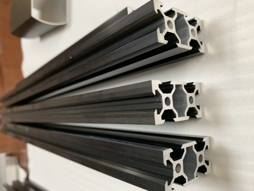
- Features in the extrusion. Card guides, screw channels, board stand-offs and cable routing can be extruded into the section. On a GPU card, the mounting geometry is as much of a problem as the thermal one.
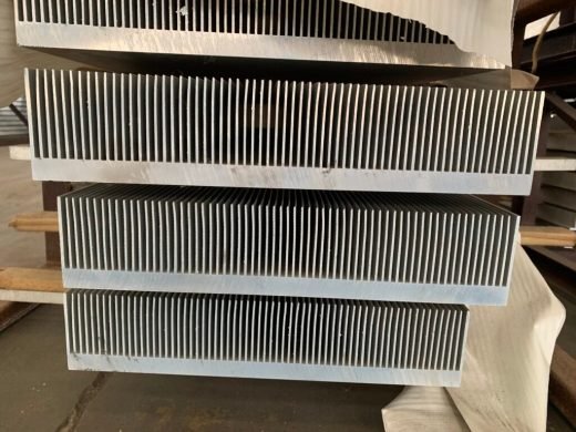
The ceiling on extruded fin density is set by the die, not by the drawing you send. As a guide: fin tip thickness 0.5 mm or more as-extruded, fin height to 50 mm as standard and to 80 mm on a dedicated die, fin pitch 2.5 mm as standard with 1.5 mm as the practical minimum, base thickness 2–20 mm, section width 10–300 mm on standard presses and to 420 mm on the large press. Where a design needs more surface area than those limits allow, CNC skiving produces fins of 0.2–0.4 mm, and bonded or inserted fins cover the very large sections.
Send the thermal map, not just the drawing
The most common cause of a lost month on an AI thermal program is a quote request that contains a drawing but no thermal specification. A drawing tells us the shape. It does not tell us why the shape is that shape, and on a high-power part the shape is downstream of the physics.
What we need to quote properly:
- power per package, in watts, and the number of packages on the card or board
- the die footprint and, where available, the hotspot map across it — not just the average
- the thermal interface material you have selected, and its rated conductivity at bond-line thickness
- cooling mode: air, with the airflow or face velocity available; or liquid, with coolant type, flow rate, inlet temperature and the pressure-drop budget
- ambient, maximum junction temperature, and the rack or chassis envelope the part has to fit
- alloy constraints, surface treatment, and annual quantity
With those numbers the die engineer proposes two or three section concepts — extruded fin stack, skived fins, or a channeled cold plate — and states what each one costs in tooling and lead time. If a feature will not fill properly, or the die tongue between two fins will not survive the run, we say so before anyone cuts steel.
What actually binds fin design at the die
Fin count on a drawing is a wish; the die decides what is real, and the binding feature is not the fin — it is the tongue of die steel between two fins. That tongue has to withstand the extrusion pressure without deflecting or cracking, and the taller the fins, the more unsupported tongue there is to fail.
That is why pitch cannot be quoted independently of fin height. A fin stack under 10 mm tall holds a tight 1.5–2 mm pitch comfortably. Push fin height to 50 mm and the geometry needs roughly 3–5 mm spacing, because there is now 50 mm of die steel standing between each pair of fins. The widely repeated "extrusion can hold 15:1" rule of thumb describes a specific combination of tip thickness and height; it is not a general licence to draw 0.5 mm fins 60 mm tall, which is 120:1 and will not run.
Three practical notes from production:
- Tip thickness before pitch. A 0.5 mm tip on a 50 mm fin survives; 0.3 mm does not, because the tip has to fill before the metal behind it solidifies.
- Taper helps. A fin that tapers from a thicker root to a 0.5 mm tip is easier to run than one with parallel sides, at a thermal penalty you can calculate.
- Corner radii. Sharp internal corners concentrate stress in the die. A small radius added to a fin root frequently turns a design we would refuse into one we run every day.
The chip interface: flatness, roughness and mounting
The base is a thermal interface before it is a structural part, and as-extruded flatness is not good enough for a semiconductor. Extrusion leaves roughly 0.2 mm of deviation per 100 mm; a graphics die needs an order of magnitude better than that, so the contact face is CNC face-milled after extrusion. Our standard on these parts is 0.05 mm flatness or better at the chip face, with surface roughness of Ra 1.6 µm or finer so thermal paste spreads evenly instead of pooling.
Interface resistance is proportional to bond-line thickness and inversely proportional to the conductivity of the interface material. As a working figure, with a typical thermal paste or gap pad, every additional 10 µm of bond line costs roughly 0.01–0.03 K·cm²/W. That looks small until it is multiplied by the flux entering the base: on a package dissipating several hundred watts through a footprint of a few hundred square millimeters, the difference between a milled contact face and an as-extruded one is no longer a rounding error. That is the whole reason the tolerance is on the drawing.
Mounting features are extruded into the section where the geometry allows: screw channels, card guides, stand-offs. Where a customer concentrates heat at a specific location rather than spreading it across the base, we can extrude a semicircular groove for a heat pipe in the common 6 mm, 8 mm and 10 mm diameters.
Surface treatment following the interface is functional, not decorative. The chip contact face is normally left bare — any coating adds a layer in the thermal path. Fins are black anodized in AA10 or AA15 where radiation or corrosion resistance is wanted. Hard-coat anodizing is rarely specified on these parts and is quoted on request rather than offered as a standard option.
Liquid cooling: extruded channels and friction stir welding
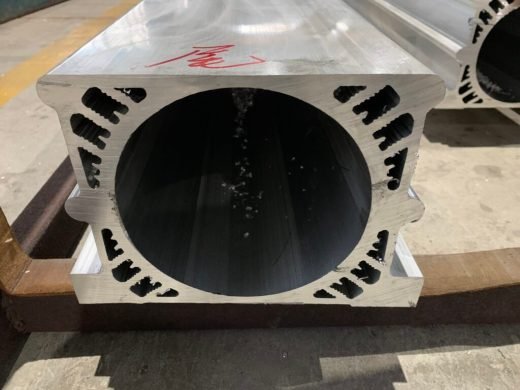
Where air is no longer the answer, the part is a cold plate. We extrude the body as a channeled section with 3–8 mm internal channels, close the ends, and join the cover by friction stir welding — a solid-state process that stirs the aluminum into a bond without melting it, so there is no filler metal, no flux and no porosity in the weld zone to open up under thermal cycling. Cold plates are rated 0.5–1.5 MPa working pressure with a burst rating of at least 3.0 MPa, and every unit is pressure-tested at 250 kPa for 60 seconds, with leakage required to stay below 30 Pa.
Two design decisions dominate performance on a GPU cold plate:
- Serpentine versus parallel channels. A single serpentine path is predictable and gives even flow, at higher pressure drop. Parallel paths lower the pressure drop but are vulnerable to maldistribution, so one part of the die gets starved while another is over-cooled. On a part with a hotspot map as uneven as a graphics die, maldistribution shows up directly in junction temperature.
- Channel cross-section versus pump power. Higher flow velocity improves the heat-transfer coefficient and costs pressure drop roughly with the square of velocity. The practical design point comes from your loop budget, which is why the pressure-drop figure is on our document request list and not an optional extra.
Tell us the coolant, the flow rate, the inlet temperature, the pressure-drop budget and the port geometry, and we will propose a channel layout before the die is cut.
Export, inspection and documents for AI server programs
Every order ships with a mill test certificate to GB/T 5237, EN 755-9 or ASTM B221 carrying chemical composition, mechanical properties and dimensional records, plus a dimensional inspection report for machined features. Extrusion weight tolerance is ±10%, which matters on a program priced by weight. Minimum order is 500 kg per profile; die tooling is quoted for the project.
For customs, extruded profiles are normally classified under HS 7604 and machined aluminum articles commonly under 7616.99 — but classification is your customs broker's determination, not ours, and we will supply the composition and processing route data they need to make it.
For EU-bound shipments, note that the CBAM definitive regime applies from 1 January 2026. Importers above 50 tonnes a year must hold authorized CBAM declarant status and report embedded emissions per consignment. Send us the data fields your declarant requires and we will confirm, before you place the order, which of them the mill can provide against actual production records.
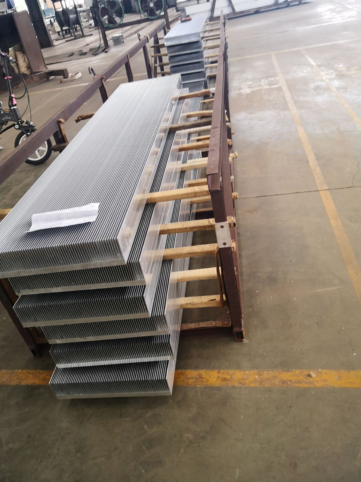
Packing is built for long, thin sections: interleaved profiles, board and foam edge protection, strapped bundles. A 20 ft container takes lengths up to 5.85 m, so 6 m sections ship in a 40 ft container or are cut to length below 5.85 m — a practical decision to settle at quotation, because it changes both freight and the number of joints in the finished assembly. Terms are FOB Shenzhen or Guangzhou, CIF on request.

 Industrial Aluminum