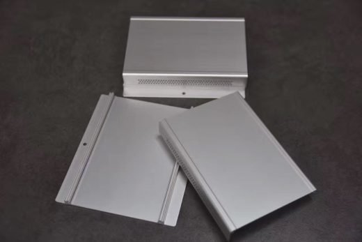
A solar inverter housing or optimizer bracket has to do three jobs at once: spread heat from the power electronics, keep IP-rated weather sealing for 20+ years of UV and salt-fog exposure, and machine to a tolerance that lets the cover drop on without rework. That is why Tier-1 inverter makers build the housing from an extruded aluminum section and finish it with multi-axis CNC machining in a single fixture, rather than weld sheet-metal boxes. This page shows how we do it at LINKEDALU METAL: alloy and temper selection for outdoor service, CNC tolerances we hold every day (sawing ±0.1 mm, hole position ±0.05 mm, milled flatness 0.05 mm), surface finish selection for outdoor service, and the workflow from drawing to container.
Why Extruded Aluminum for Solar Inverter Housings?
An extruded aluminum section gives the housing a built-in heat-spreading geometry. The die can put fins on the back of the housing, mounting bosses on the sides and a flat sealing face on the front in one continuous profile, without welds or fasteners. CNC machining then opens the cable entries, drills the mounting pattern and mills the cover-sealing face to a tolerance that sheet metal struggles to match.
The numbers matter. A sheet-metal inverter box typically uses 1.2 mm galvanized steel at 6.5 kg/m², has 18–24 fasteners around the cover, and needs a silicone bead plus a foam gasket to reach IP65. An equivalent extruded aluminum housing at 2.5 mm wall weighs 2.1 kg/m², uses 8 captive screws, and reaches IP65 with a single EPDM gasket on a milled face. The aluminum version dissipates 35–40 % more heat through the fin root because the section is one thermal path, not a steel box bolted to a separate aluminum heat sink.
The catch is that extrusion requires commitment: a new profile needs a die, and die tooling is quoted for the project and amortized over the part volume. For runs above 5,000 housings per year the math almost always favors extrusion. Below that, we will tell you to consider sheet metal or a deep-drawn alternative — we run both, but we will not sell you a die you cannot pay back.
What Alloys and Tempers Do You Use for Inverter Housings and Optimizer Brackets?
| Part | Alloy / Temper | Why |
|---|
| Housing body (visible, finned) | 6063-T6 | Best anodizing color stability; extrudable to thin 1.5 mm walls; thermal conductivity ~200 W/m·K |
| Mounting bracket, optimizer bracket | 6061-T6 | Yield 276 MPa for thread inserts and load-bearing rails; better machinability than 6063 |
| Welded sub-frame or pole-mount structure | 6005A-T6 | Weldable without losing strength in the HAZ; structural-grade (available on request) |
| Heat-spreading baseplate under power electronics | 6063-T6 or 6061-T6, anodized | One thermal path from the power electronics to the fin root; hard-coat anodizing on request |
| Cover (separate part, machined flat) | 6063-T5 or 6061-T6 plate | Plate stock CNC machined, then matched to housing face |
For coastal or salt-air sites, every alloy above also accepts a chromate conversion underlayer before coating. This adds 0.5–1.5 µm of conversion coating and improves coating adhesion and corrosion performance without changing part dimensions.
What CNC Tolerances Do You Hold on Inverter Housings?
| Operation | Standard tolerance | Typical use |
|---|
| Precision sawing (straight or miter) | ±0.1 mm | Length stops, miter joints at corners |
| CNC drilling | ±0.05 mm hole position | Mounting patterns, cable glands, fasteners |
| CNC milling — flatness on sealing face | 0.05 mm over the machined face | Cover-to-housing seal surface |
| Thread tapping | M3 to M16, internal, 6H class | Cover screws, mounting to rail or wall |
| Surface roughness on sealing faces | Ra 0.8 µm (fine) to Ra 1.6 µm (standard) | Gasket contact surfaces |
| Maximum profile length | 6 m standard; 12 m on long-bed equipment | Long rail-format inverter housings |
| Bore tolerances (cable glands, sensor mounts) | H7 (+0.015 / 0 mm on 30 mm bore) | Press-fit components |
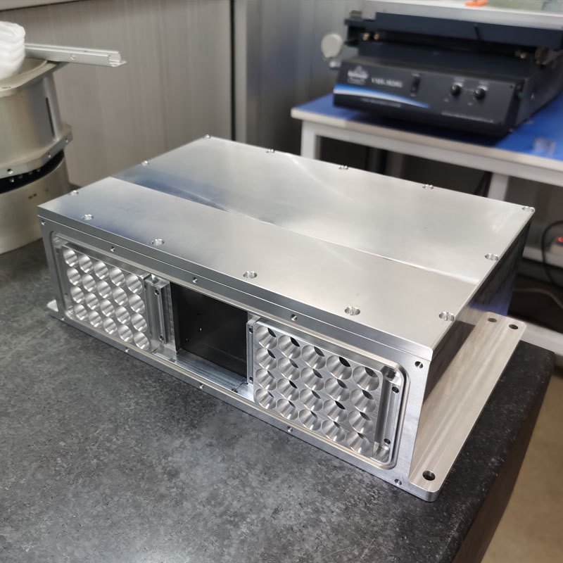
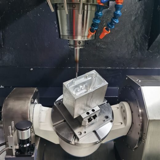
All drilling and milling of cover-sealing faces, mounting holes and cable entries is done in a single fixture setup on a 3- or 4-axis CNC center. That keeps the relationship between the gasket groove and the bolt holes governed by the machine's positioning accuracy, not by how accurately an operator re-clamps the part between operations.
What Surface Finish Survives 20+ Years Outdoors?
Two finishes cover most outdoor inverter applications. We pick based on visual priority and atmosphere severity, not cost.
Anodizing (Type II, 10–25 µm)
The default for visible housings. Clear anodizing on 6063-T6 holds its color for 15+ years in temperate climates; champagne and black anodizing are color-stable for 20+ years. The anodic layer is part of the aluminum itself, so it cannot peel, and it does not chip at the edges the way an applied coating can.
Powder Coating (60–120 µm polyester or PVDF)
Specified where the atmosphere is harder on the finish than anodizing will tolerate — coastal, industrial or desert sites — or where a specific RAL colour is required. Applied over a chromate conversion underlayer for adhesion. PVDF carries the longer colour-and-gloss warranty of the two; polyester is the lower-cost option for less exposed installations. Both are a cost premium over anodizing and are quoted per project rather than offered as a default.
Hard-coat anodizing is available where a part also serves as a heat-spreading baseplate, but it is rarely specified on inverter housings and is quoted on request.
How Do You Machine an Inverter Housing Without Warping?
Three controls, applied together, keep the housing within tolerance after machining.
- Rough, stress-relieve, finish. The housing body is rough-machined with 0.3–0.5 mm stock left on the cover-sealing face and any large flat. It is then sent through a thermal stress-relief cycle (typically 1 h at 350 °C for 6063, slower cooling). Finish machining then removes the released-stress layer to final dimension.
- Single-fixture machining. The cover-sealing face, mounting holes and cable entries are machined in one setup on a 3- or 4-axis center. Flatness and hole position stay tied to one datum — the machine's own positioning accuracy — instead of accumulating error from re-clamping.
- Soft jaws and expanding mandrels on hollow sections. A rigid clamp on a thin-walled aluminum housing will pull the wall oval by 0.05–0.10 mm, which is enough to leak. Pie-shaped soft jaws and expanding mandrels spread clamping force around the bore or circumference, so the part holds shape while features are machined.
The result, measured on a 1.5 m housing: 0.05 mm flatness on the cover-sealing face, ±0.05 mm on mounting hole positions, and a leak-test pass rate above 99 % on the first article.
How Do You Keep an Inverter Housing Weather-Tight After Machining?
IP65 is achievable on a CNC-machined aluminum housing when three conditions are met:
- The cover-sealing face is milled flat to 0.05 mm with surface roughness Ra 0.8 µm or finer.
- A continuous EPDM or silicone gasket groove is cut in the same setup, so the gasket sits on the same datum as the bolt holes.
- Cable entries use IP-rated gland plates or compression fittings, not raw drilled holes.
We run a 100 % leak-check on every housing lot: pressurize the housing to 30 kPa for 60 seconds, monitor pressure drop. Any drop above 50 Pa rejects the part. For IP67 or higher ratings, we add a second gasket path on the cable-entry plate and re-test at the rated immersion depth.
What Does the Workflow Look Like from Drawing to Delivery?
| Step | Activity | Typical duration |
|---|
| 1. Drawing review | STEP / IGES / DWG / PDF checked for extrudability, tolerances, wall thickness and corner radius | 1 working day |
| 2. DFM feedback | Design-for-manufacturability report with cost-down suggestions (orientation, tolerances, fastener placement) | 1–2 working days |
| 3. Extrusion die design & cut | H13 die, nitrided, balanced flow; sample extrusions produced on the extrusion press | 10–15 working days for a new die |
| 4. Prototyping | CNC machining in 3- or 4-axis setup, prototype lot of 1–10 pieces, full inspection report | 3–7 working days |
| 5. First-article inspection | CMM dimensional check, finish validation on sample parts, IP-rating leak test | 2 working days |
| 6. Mass production | 100 % in-process audit, full final dimensional and visual inspection, batch inspection report | 15–25 days after die approval |
| 7. Packing & delivery | Individual wrap, pearl-cotton padding, export carton or seaworthy crate; FOB Shenzhen / Guangzhou (CIF on request) | 1–2 working days |
Material certificates for the aluminum billet (chemical composition and mechanical properties) are supplied with every shipment. Surface-finish thickness records and CMM inspection data are issued on request for OEM customers.
Production site: Foshan, Guangdong, China. Die design, extrusion, finishing and fabrication run on one site, and containers load at Shenzhen (Yantian / Shekou) or Guangzhou; that is why we quote FOB Shenzhen / Guangzhou by default, and can also quote CIF to most major ports in Europe, the Americas, the Middle East and Africa on request. Our Santiago office serves customers throughout South America in their own time zone.
Get a quote for your inverter housing or optimizer bracket
Send a STEP file and your surface finish specification. We will return a DFM review, an itemized quotation and prototype lead time within 24 hours.
Request a quote · All CNC Machining Parts · CNC Machining of Aluminum Profiles

 CNC Machining Parts