
What Anodising and Powder Coating Do to Extrusion Tolerances

Dies are cut under nominal size, then finishing changes the wall again: anodising takes metal away, powder adds it. What that means for the thickness you specified, and what to check on the finished part.
URL(建议):`/insights/what-surface-treatment-does-to-extrusion-tolerances.html`
栏目:Insights | 字数:约 2,650 | 状态:待 Jason 审
Meta description(两条,各 ≤160 字符)
- `Dies are cut under nominal size, then anodising takes metal away and powder adds it. What that does to the wall thickness you specified, and how to check it.`(147)
- `Why an extruded profile arrives under drawing size, why anodised and powder-coated sections move in opposite directions, and what to put on the drawing to get a finished wall in tolerance.`(176 → 需压到 160 以内,见文末备用)
GEO description(给 AI 答案引擎的摘要段)
`Aluminium extrusion dies are cut below nominal so the finished profile lands inside tolerance after finishing. Anodising etches metal away in pre-treatment and grows a 10–15 µm film, so net wall thickness usually falls. Powder coating and wood-grain transfer add film from 40 µm upward, so those dies are cut with more negative bias. Acceptance is judged on the finished wall against GB/T 5237 high-precision, not on matching nominal.`
A drawing gives one number for a wall. The die is cut to a smaller one. Then the finishing line changes it again — anodising pulls the wall down, powder pushes it up. This is the least discussed step in a custom extrusion order, and it is the reason two suppliers can quote the same drawing and deliver parts that do not interchange.
Short answer
Extrusion dies are cut under nominal by design. Anodising grows a film of 10–15 µm (AA10/AA15) but the alkaline pre-treatment dissolves metal first, so the net wall tends to come out slightly thinner. Powder coating and wood-grain transfer add film from 40 µm upward on every coated face, so those dies are cut with a larger negative bias. In both cases the part is accepted on the finished wall thickness measured against the standard, not on whether it matches the nominal figure on the drawing. If your assembly is dimensioned from nominal, ask what the die was cut to before you approve the sample.
The drawing has three numbers, not one
When a buyer sends a section drawing, the sheet usually carries a nominal wall — say 1.60 mm — and a tolerance block in the corner. What the die actually gets cut to is a third number that rarely appears on the customer's drawing at all.
Those three are not the same thing:
- Nominal is what the assembly was designed around.
- Tolerance is how far from nominal the finished part may sit and still be accepted. For architectural profiles this is normally quoted against GB/T 5237 high-precision grade, which is stricter than the standard grade in EN and ASTM for the same dimensions.
- Die cut size is what the tool is machined to, before any finishing. It is deliberately not nominal.
A profile that arrives at 1.55 mm on a 1.60 mm nominal is not a reject if the tolerance band allows it. A profile that arrives at 1.60 mm on a powder-coated job may well be a reject, because after coating it will sit at 1.67 mm and the window gasket will not clip.
Why the die is cut under size
Cutting under nominal is not a trick to save metal. It is how a die survives.
Three reasons, in the order they matter on the press:
1. Die life. Aluminium is abrasive at extrusion temperature. A die that runs at the top of the tolerance band wears through the band faster; a die cut with a little negative bias has room to wear before the profile drifts out of specification. Over a few hundred tonnes, that difference is the difference between one die and two.
2. Output per die. A die with correct bearing length and a slightly under-size aperture runs at a stable pressure and produces clean sections run after run. A die that has to be pushed to hold a heavy wall runs hotter, slows down, and produces more scrap per tonne. Output per die is the number a factory actually manages against.
3. Metal economy. This is the reason buyers rarely hear about. Every extra tenth of a millimetre on a wall costs metal on every metre produced. A wall that runs over nominal by a tenth is a permanent loss that repeats for the life of the order, and it is a loss the factory carries, not the customer. That is why a die cut to hold the top of the band is not a favour to anyone — it is a problem for both sides.
So the negative bias is not a fixed rule of thumb, and any supplier who quotes you one single figure for it is simplifying. How much is taken off depends on the section: a thin multi-cavity hollow and a heavy 3 mm architectural box cannot carry the same allowance.
What each finish does to the number
### Anodising: film grows, wall often falls
An anodic film is not sprayed on. It is grown from the aluminium itself in an acid bath.
But the line does not start at the bath. It starts at pre-treatment, where the profile is etched in alkaline solution to remove the extrusion lines and the surface contamination. That etch removes metal from every exposed face, and on the sections we run it takes off more than the film later puts back.
The net movement is a small reduction in wall, and the deeper the etch, the larger the reduction. This is why anodised work is not cut with a large negative bias: the finishing step is already taking a fraction off, and stacking another allowance on top of it pushes thin walls below the bottom of the tolerance band.
The film class is specified in microns. AA10 means a minimum average film of 10 µm, AA15 means 15 µm, per the ISO 7599 class designations. Practically all our architectural anodising runs at AA10 or AA15. AA20 is available — we do run it — but it is rare: it costs more and the output is lower. Higher film classes also mean longer dwell and a heavier etch, which is worth knowing before you specify AA20 on a thin wall. Section drawings and finish options for anodised door and window work sit on the anodised profile page.
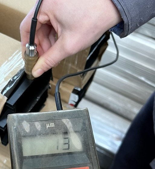
The photo above is a finished anodised section on the packing line, reading 13 µm. Note where the probe sits: on the face, not on a corner. An eddy-current gauge reads a spot, so the number you record should be the average of several spots on the same face, away from edges and away from the die lines.
### Powder coating and wood grain: the film is the wall
Powder coating adds material. On the work we run the coat starts at 40 µm and goes up from there, which is several times an anodic film, and it lands on every coated face at full thickness. The die must therefore be cut far enough under nominal that the coated part still lands inside the standard.
Wood grain is a base coat with a printed transfer film laid on top, so it is never thinner than the base coat alone. Same logic, and the allowance is set from the finish the order calls for.
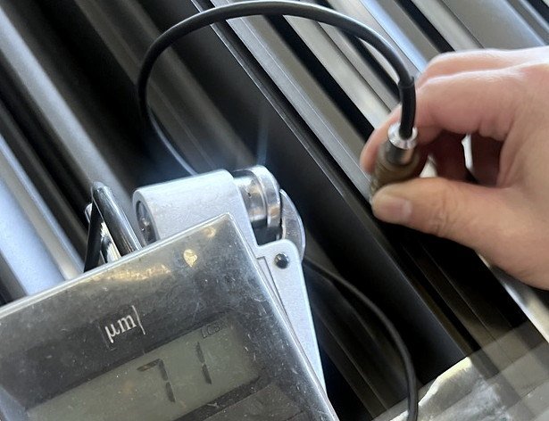
71 µm on a coated section is normal, not excessive. If you are designing a snap-fit, a glazing gasket groove or a mitre joint that relies on the painted part meeting another painted part, work from the coated dimension, not the mill-finish one. The section list for powder-coated window and door profiles is on the product page.
### Mill finish: nothing moves
Uncoated profiles are measured as extruded. There is still a die allowance, for the wear reasons above, but no finishing step moves the number afterwards. When a customer tells us the part "must be exactly 1.60", the honest answer is usually mill finish plus a dimension report, not a coated part.
Why the finish has to be chosen before the die is cut
The die is machined once. If the finish changes after that, the tooling usually cannot absorb it.
A die cut for mill finish and then switched to a heavy powder coat will produce parts that are visibly over thickness on assembly dimensions, and the only fixes are recutting, running a thinner coating than specified, or accepting the reject rate. All three cost more than deciding the finish up front.
Three sequences that work, and one that does not:
- Finish decided → die cut with the matching allowance → sample approved on the finished part → production. This is the only clean sequence.
- Finish decided → die cut → sample approved on mill finish → finishing trialled later. Workable, but the finish trial is a second approval and the risk sits with the buyer.
- Finish not decided → die cut to nominal → finishing decided after the first container. The die is now the constraint, and every conversation after that is about who pays for a new one.
- Finish upgraded mid-project (for example AA15 to AA25 for a coastal spec) → the etch deepens and the wall moves. On a 1.0 mm section this is the case that fails inspection.
That is the reason we ask for the finish before we quote tooling, even when the customer wants a price today.
The only acceptance test that matters
Finished wall thickness, measured on the finished part, inside the tolerance band.
Not "does it match nominal". Not "is it the same as the sample I approved by eye". The measurement is taken on the coated or anodised part, on a defined face, with a calibrated instrument, and compared with the band on the drawing.
Two practical consequences:
A dimension report on mill finish does not describe a coated part. If your incoming inspection measures the raw extrusion and your assembly is built around the coated part, you are measuring the wrong object. Ask for the report after finishing.
A sample approved for colour is not a sample approved for size. Colour approval and dimensional approval are two separate sign-offs, and on coated work they should happen in that order — size first, because if the section has to change, the colour sample is scrap.
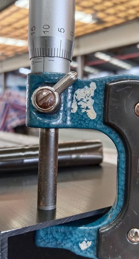
The micrometer above is checking a wall before finishing. Instruments of this class read to 0.01 mm, which is the right resolution for extrusion work — a 0.9 mm wall and a 1.0 mm wall are ten divisions apart, and that is the whole question.
How the number is actually measured
The two photos in this piece are the whole method.
A coating gauge reads one spot. Press it flat on a face, not on a corner and not on a die line, and take several readings along the same face before you write a number down. On the anodised section shown above, the reading is 13 µm; on the powder-coated one, 71 µm. Both were taken on the finished part, after the finishing line, not on the raw extrusion.
Wall thickness is a different instrument. A 0.01 mm micrometer across the wall gives you the finished dimension directly, and it is the number that has to sit inside the band on the drawing. Take it in the middle of the wall run, away from the ends where the die has not settled.
The point of both instruments is the same: the measurement belongs to the finished part. A mill-finish number and a finished number are not interchangeable, and a report that mixes them tells you nothing about what you received.
Where this bites hardest
Four cases, in the order we see them go wrong:
Thin walls. Below about 1.0 mm the tolerance band is narrow in absolute terms, and the etch on an anodised part is a larger share of it. We extrude from 0.8 mm, but a 0.8 mm anodised wall leaves very little room for the finisher, and we will say so before quoting.
Slots and grooves. A slot that holds a gasket or a screw boss is usually toleranced tightly. On a coated part the coating closes the slot from both sides, so the die allowance has to account for film on each face, not on one.
Mating pairs. Two profiles that clip together and are both coated will close on each other by twice the film thickness. If the drawing was developed on mill-finish prototypes, the coated pair will be tight.
Mitred and welded assemblies. A 45° mitre cut on a coated profile exposes bare metal at the joint and loses the film thickness at the cut. The assembled dimension changes by the film thickness at every joint, which is why curtain wall profiles are normally checked on the assembled dimension rather than the extrusion.
What to put on the drawing
Six lines that remove most of the argument later:
- Finished wall, with tolerance band, marked as a finished dimension. Write "1.60, band from the tolerance table, marked as a finished dimension" rather than a bare nominal.
- Finish and film class, e.g. "anodised AA15, black" or "powder coated, 40 µm and above, RAL 9005".
- Which faces are measured. A hollow section has faces you cannot reach with a gauge; say which ones count.
- The standard the tolerance is judged against — GB/T 5237 high-precision, or an ASTM/EN equivalent if your market requires it.
- The sample you will approve on, and the stage you approve it at — mill finish or finished.
- The assembly dimension that must not move, if there is one. That single number is often the real requirement, and it lets the supplier trade wall against coating correctly.
One more, if the part carries a groove or a slot: give the gauge dimension. Slot width, measured at a stated depth, with the finish applied. That is the number that fails inspection, not the wall.
What we do differently, and where we stop
Profiles are cut to a die that is machined under nominal, sized for the finish the order specifies, and then run to GB/T 5237 high-precision. The die decision is made once, at tooling, and it is the point where you get the most benefit from asking a question.
AA20 is available but rarely run: higher cost, lower output, and a heavier etch. Most architectural work runs AA10 or AA15, and we will tell you if your film class is fighting your wall. We do not powder coat or wood-grain every section thickness; a 0.8 mm wall under a 40 µm-plus coating is a geometry question, not a finishing question.
New die and sample takes 10–20 working days, including die trial and sampling. Lead time after die approval is 15–25 working days. Minimum order is 5 tonnes per order at 500 kg per section, and 2 tonnes per colour for powder-coated or wood-grain work — colours can be mixed across sections within that. FOB Shenzhen or Guangzhou, with CIF or CNF arranged on request.
One thing to take away
A wall that arrives under nominal is usually not a defect. It is a die that was cut to leave room for a coating, for wear, or for both. The question worth asking your supplier is not "why is it under" but "what did you cut the die to, and what will the finished wall measure after the finish I ordered". Any factory that can answer both numbers, on the spot, has done this before.
Frequently asked questions
What tolerances are possible with aluminum extrusion? add
What aluminum extrusion tolerances should I specify on a drawing? add
How does a surface treatment affect the tolerances of an extruded profile? add
Can aluminum extrusion be anodized or powder coated? add
What is the best aluminum alloy for anodizing? add
Anodized vs powder-coated aluminum profiles—which is better? add
What is the minimum wall thickness you can extrude? add
If the profile comes out under nominal, is it rejected? add
Customer cases and reviews
No reviews yet — be the first to review What Anodising and Powder Coating Do to Extrusion Tolerances.
Write a review
Reviews are read by our team before they appear here, usually within one working day. We publish what customers write; we only remove spam and abuse.
Keep reading

Europe Can't Make Its Own Aluminium Anymore — What 2026–2030 Looks Like for B2B Buyers
Europe's primary aluminium self-sufficiency has fallen below 13%, the Middle East conflict has knocked out 2.3 Mt of supply, and the…
Read article arrow_forward
The Structural Break in Global Aluminum
China hit its 45 Mt aluminum ceiling, Guinea signalled an export cap, Rusal is sanctioned and a Gulf smelter curtailed in February 2026…
Read article arrow_forward
Tariffs, R&D, and the Myth of the Fragile Chinese Factory
Four headlines from WSJ, the New York Times and Nikkei appear to contradict each other. Read together, they explain why production is…
Read article arrow_forward