Designing an Extruded Heat Sink Around the Physics
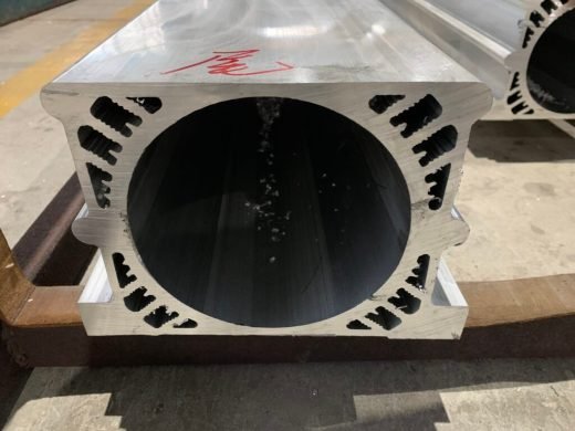
Aluminum extrusion handles power electronics cooling, from 10 kW string inverters up to EV battery packs, but only when the profile is designed around both the heat path and the limits of the extrusion press. The right approach depends on what you are cooling: a passive IGBT heat sink, a solar inverter housing, or a liquid-cooled battery cold plate.
Start with the thermal specification. Send us heat load in watts, ambient temperature, maximum junction temperature and the cooling mode, whether natural convection, forced air or liquid. If you have a CFD model, send it. If you do not, tell us the power and we will work backward to a profile.
Alloy Selection for Power Electronics
6063-T5 is the standard for extruded heat sinks, with a thermal conductivity of roughly 200 W/m·K and a yield strength of about 145 MPa. 6061-T6 is used where the profile is structural or sees high internal pressure, and 6005A-T6 where the assembly is welded. Profile widths run from 10 mm to 300 mm on standard presses and up to 420 mm on a large press.
Fin Geometry and Base Thickness
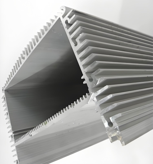
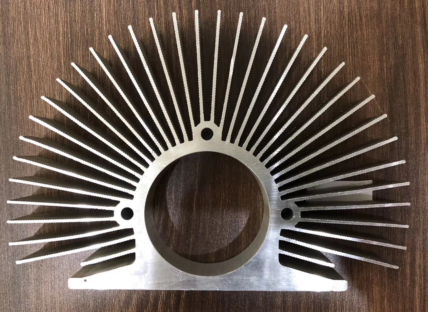
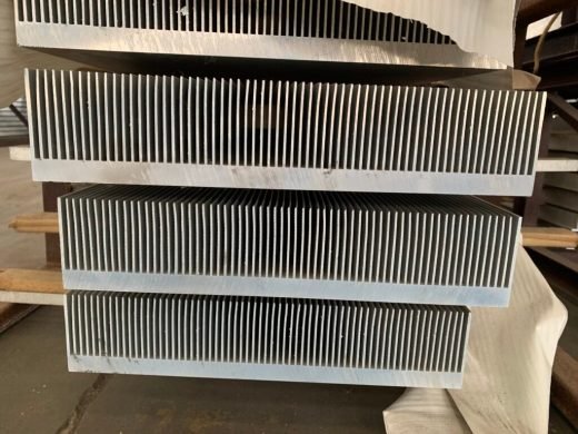
Fin pitch is normally 2.5 mm or wider, with 1.5 mm as the practical minimum, and fin height goes up to 50 mm as standard or 80 mm with dedicated die design. Base thickness runs from 2 mm to 20 mm; for IGBT mounting, a base of 8 mm to 15 mm is typical because it spreads heat laterally before the fins remove it. Tolerance is held to EN 755-9, with DIN 1748 as the legacy German reference.
IGBT Module Mounting: What the Base Must Do
The base is a thermal interface, and its geometry matters as much as its alloy.
- Surface flatness: 0.05 mm or better. Every 0.01 mm of extra gap adds roughly 0.5 to 1.0 K of thermal resistance.
- Surface roughness: Ra 1.6 µm or finer, so thermal paste spreads evenly without pooling.
- Flatness method: CNC face milling after extrusion. As-extruded flatness of about 0.2 mm per 100 mm is not good enough for a semiconductor interface.
Where an inverter concentrates heat at specific locations instead of spreading it evenly, we can extrude a semi-circular groove into the base for a heat pipe, in the common diameters of 6 mm, 8 mm and 10 mm.
Industrial VFDs and UPS Systems
For industrial drives and UPS units, power dissipation per module is typically 50 to 150 W, with total heat sink dissipation of 200 to 800 W depending on drive rating. These applications tend toward larger profiles, thicker bases and machined mounting surfaces with precisely located hole patterns.
Liquid Cold Plates for EV Battery Cooling
Liquid cooling moves the heat load to a cold plate with internal channels. Extruded channel diameters run from 3 mm to 8 mm. The channels are sealed at the ends, and friction stir welding is the default for EV cold plates: a rotating tool plunges into the aluminum and stirs the metal into a solid-state bond with no filler material and no porosity, which survives thermal cycling. Cold plates operate at 0.5 to 1.5 MPa working pressure with a burst rating of at least 3.0 MPa.
Leak Testing and Surface Finish
Every cold plate is pressure tested at 250 kPa for 60 seconds with leakage below 30 Pa. Surface finishes include mill, black anodized with an emissivity of 0.85 to 0.90, hard anodized and sandblasted. Anodizing thickness is 10 to 25 µm per Qualanod practice.
Ordering and Lead Times
Standard length is 6 m extruded, cut to length from 100 mm. Minimum order is 300 kg on a new die. Lead time to first sample on a new die is 10 to 15 working days, and 7 to 10 working days for repeat orders. Send the drawing early so a manufacturability review happens before tooling is cut. Production runs under an ISO 9001:2015 quality system.

 Industrial Aluminum