Aluminum Parts That Move
Robot arms move, AGVs carry loads and vision systems inspect at micron-level accuracy. The aluminum parts inside those machines are not passive: they are under stress, in motion, and they set the ceiling on how precise the whole system can be. Linkedalu Metal Group Co., Ltd machines those components in the low and medium volumes robotics companies actually buy.
These parts share a profile: they are not catalog items, they usually have thin walls and tight bores, several faces must be square to each other, and the order is often fifty pieces this month and a hundred next quarter. Send a STEP file and the part is machined, anodized and shipped from one supplier.
Robot Arm Joint Housings and Connecting Arms
Joint housings form the skeleton of a collaborative or industrial arm. They are typically cylindrical or box-shaped with a bearing bore at each end and mounting flanges on the sides. The recurring problem is that the wall may be 3 mm or less, and as soon as the part is clamped for boring it deforms slightly. The bore is finished, the clamp is released, and the hole springs back out of round, so the bearing does not seat properly and the joint has play from day one.
The answer is fixturing. Pie-shaped soft jaws and expanding mandrels spread clamping force evenly around the circumference, holding the part without squeezing it oval. Bearing bores at both ends are finish-bored in one setup on a 4-axis machine, so coaxiality is governed by the machine's own alignment rather than by re-fixturing, and the flange faces are milled flat in the same setup so they stay perpendicular to the bore axis.
Linear Actuator Base Plates and Stress Relief
A linear module base plate is the long aluminum plate that everything bolts to: the rail on top, the bearing blocks and the motor mount at one end. A plate around 1.5 m long behaves well during machining and badly afterwards. Roughing cuts release residual stress left in the plate by the aluminum mill, and the remainder comes out slowly, so the plate can bow by as much as 0.1 mm over the following weeks, which is enough to make a precision stage bind.
We rough-machine the plate leaving about 0.5 mm on critical faces, send it through a thermal stress-relief cycle, then finish-machine. The rail mounting surface and the bearing housing seats are milled in one setup, and flatness is checked on a granite surface plate with a dial indicator. For a plate 1.5 m long we hold 0.05 mm flatness. Rail bolt holes are thread-milled rather than tapped so they sit exactly on position and perpendicular to the mounting surface.
Vision System Frames and Camera Mounts
Machine vision is used for inspection, pick-and-place and autonomous navigation, and the camera and light are carried on aluminum frames that position them at precise angles and distances from the target. If the mount is off by 0.2 mm, the calibration is off. These frames commonly have several mounting faces at different angles for the camera, the light and the gantry.
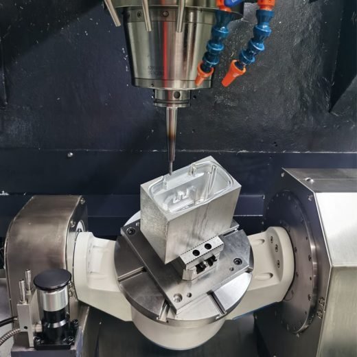
We machine them on 3, 4 and 5-axis CNC so multiple faces can be reached without breaking the setup. All critical mounting holes are machined from the same datum, so their relative positions are controlled by the machine's positioning accuracy rather than by how carefully the part was re-clamped. Edges are deburred so cable routing slots cannot cut wiring. Anodizing is done in-house; black anodized frames are common on vision systems because they reduce stray reflections.
AGV and AMR Chassis Plates
Autonomous mobile robots run on aluminum chassis built from a base plate, a top deck, side panels and a battery compartment frame. A typical base plate might be 1,200 mm by 800 mm with mounting patterns for drive wheels, casters, lift mechanisms and sensor brackets. A bowed plate makes the vehicle track crooked, and an inaccurate drive unit hole pattern wears the tires unevenly.
Large plates are held on a vacuum table so no clamp distorts the edges, and all hole patterns are programmed from a single reference corner, so drive unit, caster and sensor bracket holes relate back to the same origin with no accumulated error. Most AGV parts are 6061-T6.
Sensor Brackets and Precision Fixtures
Small precise parts position sensors, cameras and alignment tools on an automated line. A laser distance sensor needs its bracket to hold it at exactly the right height and angle, and a proximity switch needs its mounting hole dead center on the target path. Parts might be 50 mm by 30 mm by 20 mm with a dowel pin hole at 6H7, which leaves only microns of clearance.
These are batch-machined on the CNC with multiple workholding stations. Once the program is proven on the first piece the rest come out identical, dowel holes are finish-reamed rather than simply drilled, and threads are milled for consistency.
Tolerances We Hold Every Day
| Feature | What we hold | How it is checked |
|---|
| Bearing bore diameter | H7 (+0.015 / 0 mm on 30 mm bore) | Bore gauge calibrated to ring standard |
| Bore coaxiality | 0.02 mm or better between two bearing seats | CMM or test bar with dial indicator |
| Flatness on rail mounting surface | 0.05 mm over 1,500 mm | Granite surface plate plus dial indicator |
| Hole position | +/-0.05 mm from datum | CMM or height gauge |
| Thread quality | 6H class, no tear-out | Go / no-go thread gauge |
| Surface finish on sealing faces | Ra 0.8 to Ra 1.6 um | Surface roughness tester |
Materials stocked include 6061-T6 for general robotics, AGV parts and brackets; 7075-T6 for high-stress arm links and thin-wall structural parts; 6063-T5 for enclosure parts and cosmetic covers; and MIC-6 cast plate for flatness-critical vision bases.
Volumes, Files and Finish
CNC machining carries no tooling cost the way extrusion or die casting does, so small batches make sense. Prototype quantities and production runs in the hundreds are handled on the same equipment, with the minimum order quantity set at 50 pieces. Accepted file formats are STEP for solid geometry, IGES and Parasolid, and 2D PDF or DXF drawings for simpler parts; if only a drawing exists, the model can be created with an extra day allowed for CAD work.
Anodizing and hard anodizing are done in-house, so parts do not leave the building between machining and finishing. Cosmetic surfaces are masked during clamping with soft jaws or protective film, and finished parts are packed individually rather than thrown into a bulk bin, which avoids the scratches that cause rejection at incoming inspection.

 CNC Machining Parts