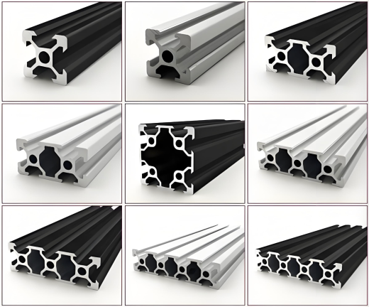
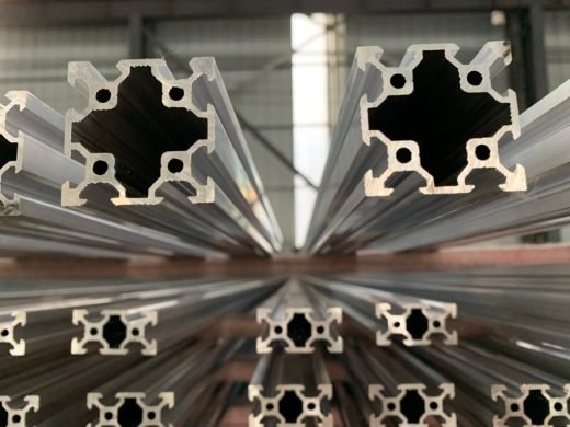
Most framing projects do not need the heaviest profile in the catalogue, and few get away with the lightest one. The 30 mm series sits in that gap: 3030 for uprights, shelf edges and guarding posts, 3060 for beams, conveyor rails and machine bases. We extrude both in 6063 or 6061, in T4, T5 or T6, and machine them to your bill of materials — or cut a die to your own section where the standard geometry does not fit the job.
Why the 30-series fits more jobs than the 20 or the 40
The 20-series is light, and it earns its place on a 3D printer frame or a bench-top enclosure. Put a loaded conveyor on it, or a shelf beam carrying a bin, and the frame moves more than the eye tolerates. The 40-series is stiff and durable, and on a guard panel or a cart frame it is more metal than the design needs — you pay for that in weight, freight and cost per metre on every bar in the frame.
In between sits the 30-series. A 3030 in a standard wall carries somewhere in the range of 50 to 150 kg at a 1 m span; where it lands inside that band depends on wall thickness and the deflection you are willing to allow. That covers most conveyor side rails, shelf beams, guarding posts and light machine bases, which is exactly where projects either over-specify or under-specify.
One rule is worth applying before anything else: choose the section from the deflection limit, not from the catalogue picture. Send us the load, the span and the deflection you can live with, and the quotation will carry the section properties (I and Z) for the profile we propose, so your engineer can run the check rather than take a rule of thumb.
3030 and 3060 in numbers
| 3030 | 3060 |
|---|
| Cross-section | 30 × 30 mm | 30 × 60 mm |
| Slot width | 6 mm (metric 30-series) | 6 mm |
| Slots | 4 — one on each face | 6 |
| Weight | roughly 0.9–1.3 kg/m depending on wall | roughly 1.8–2.5 kg/m depending on wall |
| Typical role | Uprights, shelf edges, guarding posts, cart frames | Conveyor beams, shelf beams, machine bases, longer spans |
| Hardware | M6 T-nuts and standard 30-series connectors | same |
A 6 mm slot takes M6 hardware, which is enough for brackets, panel retainers, castors, guarding mounts and cable ducts. Where a joint carries a bending moment rather than a panel load, use the end-face connection into the core bore instead of a side bracket — a side bracket in a slot is a shear connection, and it behaves like one.
Because 3060 shares its 30 mm width with 3030, a 3060 beam bolts straight to a 3030 upright on the same nuts and brackets. That is the practical reason to build a frame inside one series: the hardware stays common, so you can mix sections without mixing fastener types.
Standard framing length is 2.0 m, cut to your list.
Packaging and conveyor lines
A packaging line frame has to hold the conveyor at a working height, carry the side rails and the product guides, mount the guarding, the light curtain and the e-stop, and stay square while the line runs. That is a different requirement from a static shelf.
The load on a conveyor frame is not static. Cartons drop onto the belt, a diverter fires, a motor starts, and the frame sees that as a repeated impulse rather than a steady weight. A frame that bows 3 mm under a running load puts the belt out of alignment, and the first symptom is usually product tracking to one side rather than anything that looks like a structural failure.
Cross-members are the cheapest stiffness available. A mid-span cross-member costs one length of 3030 and two brackets; stepping up a profile size costs extra metal on every bar in the frame. On most conveyor frames the cross-member does more for alignment than the section does.
Plan the accessory stack before the BOM. Guard panels, cable ducts, sensors and e-stops all want the same slot faces, and a panel retainer and a bracket cannot share one slot. Working the accessory layout out on the drawing is much cheaper than discovering it with the frame half-built.
Reconfiguration is the whole point of a bolted system. Packaging lines change, and a bolted frame comes apart and goes back together with new sections added. A welded frame does not, and that is usually the deciding cost over a five-year horizon.
Racking, shelving and material-handling carts
Shelf frames are the simplest use of the series: 3030 uprights, 3060 beams, shelf surface on top. It works well, and it fails in two predictable ways.
The first is a beam that sags noticeably under a bin, which is a deflection problem rather than a strength problem — the beam size or the span is wrong for the load, and the fix belongs in the design. The second is a cart that rocks because the frame is not square, which is usually a straightness or a cut problem rather than a design fault. Those two symptoms look similar to a buyer and have completely different causes, which is why we ask for the measured deflection when a claim comes in.
Cart loading is harder on the frame than the static weight suggests. The castors carry the whole load, and every bump in the floor puts a bending moment into the post rather than a straight compressive one. Where a cart is moved while loaded, size the post for the moving case.
One diagonal in the back plane turns a wobbly cart into a rigid one. It is the cheapest fix in any frame, and the one most often left out. Shelf back panels and side panels then mount straight into the slot with panel retainers, no drilling.
Machine frames and equipment bases
A machine base is judged on how little it moves, and stiffness comes from the section and the geometry rather than from the alloy grade. Moving from 6063 to 6061, or from T5 to T6, raises the yield strength and does almost nothing for deflection, because deflection is governed by the modulus of elasticity, which is essentially the same across them. If a base is flexing, the size of the section is the variable to change.
Every connection in a bolted frame is a joint, and joints move. Put the main load path through end-face tapping into the profile core, and keep side brackets for panels, guards and accessories. A frame assembled entirely with side brackets will behave exactly like a frame assembled with side brackets.
Leveling feet with a defined thread and a lock nut turn a four-post base into a stable plane on a floor that is not flat. Plan the foot thread at the same time as the post, because the depth of the tapped core has to suit the stud you intend to use.
On vibration, one honest note: aluminium does not damp the way cast iron does. Where a machine is genuinely sensitive, mass and a stiff bolted structure help more than a change of profile or alloy, and a really quiet base usually means a concrete or steel sub-frame under an aluminium top frame rather than a heavier aluminium section.
Will it fit the hardware you already have?
This is the question that arrives most often from a buyer who already runs a framing system: will your 3030 take my nuts and brackets?
The honest answer depends on which system. The metric 30 mm grid is a de-facto standard, and the major European framing systems work on the same 30 mm and 45 mm grids with the same standard T-slot connector hardware, so metric 30-series brackets generally interchange. The imperial families are a different grid entirely: an inch-based 1.5 in (38.1 mm) profile with an inch slot is not interchangeable with a metric 30-series section, and a “30 series” label on a supplier’s website does not tell you which of the two you are ordering.
To confirm a match we need one of three things: the T-nut you are using, the measured slot opening, or a sample bracket. We check the slot width and the tongue geometry against the die before it is cut, and if it will not fit we say so before the order rather than letting you find out at assembly.
If nothing on the market matches what you need, that is the case for your own die.
OEM and ODM: your own section instead of a catalogue number
OEM — you have the drawing. We extrude your section: your slot geometry, your wall thickness, your core bore. It is machined to your cut list, and every bar is labelled with your part number so your crew builds by the numbers. Bar labels and packing can be supplied as your own private-label frame kit.
ODM — you have the load case, not the drawing. Give us the load, the span, the deflection limit and the envelope, and we will propose the section, including slot layout and the wall thickness that meets it. We have done this for conveyor, racking and machine-base frames, and it is usually faster than starting from a catalogue.
Dies are cut in-house, so tooling lead time sits with us rather than with a third party. MOQ is 500 kg per section, whether the section runs on a die already in our library or a new one is cut for it. We send a length from the first pressed billet as a sample before you commit to the run, which for a framing system is the only way to confirm the slot before several tonnes of profile arrive.
Extrusion is invoiced on weight, and a ±10 % tolerance on total weight is normal for custom work, so a 500 kg order can arrive between roughly 450 kg and 550 kg. We quote the weight per metre up front so the reconciliation on arrival is arithmetic rather than a dispute.
On length and freight: 2.0 m is the standard framing length and bars are also cut to your list. A 20 ft container takes up to 5.85 m, so anything longer ships in a 40 ft or comes cut to fit.
On finish: silver anodized in AA10 or AA15 is the standard for frame profiles and the most colour-stable; black anodized is available where a machine or a cleanroom calls for it, and mill finish for structure that will not be seen. Every bar in one order is anodized in a single batch, so legs and beams match.
Mill test certificates covering composition, temper and mechanical properties are issued with every lot. Manufacture is to GB/T 5237, and to ASTM or EN on request.

 Industrial Aluminum