Extrusion and Machining Under One Roof
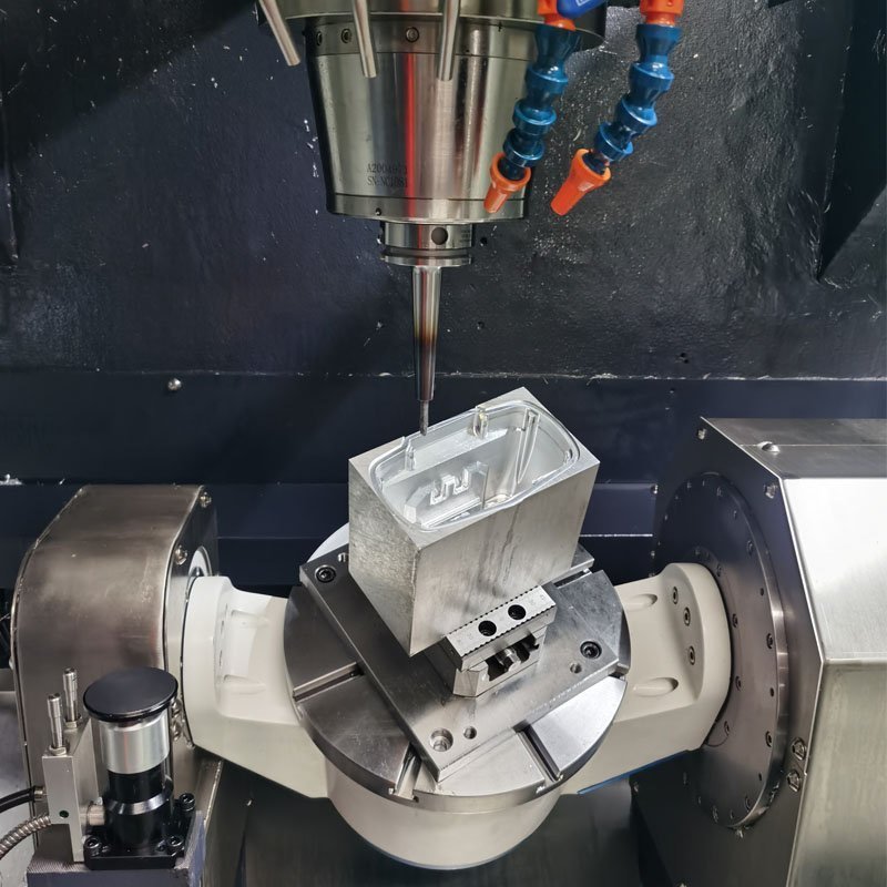
A raw aluminum profile is not a component until it has been cut, drilled, tapped and finished to the drawing. Linkedalu Metal Group Co., Ltd runs an independent CNC deep processing workshop alongside its extrusion presses, so the same facility that produces the section also machines it into a part that can be bolted straight into your machine, automation frame or structure. That removes the handling damage, freight cost and schedule risk that come with shipping raw profiles to a third-party machine shop.
Because the profile geometry and the machining process are planned together, the cross-section can be optimized for the tooling that will follow. The classic problem of a profile that machines badly at a separate shop does not arise when the die designer and the process engineer sit in the same building.
Machining Capabilities and Published Tolerances
| Process | Capability | Tolerance |
|---|
| Precision sawing | Burr-free miter and straight cuts with high surface finish | +/-0.1 mm |
| CNC drilling | Multi-surface drilling in a single fixture setup for alignment | +/-0.05 mm |
| Thread tapping | Metric and standard internal threads for hardware fastening | M3 to M16 |
| CNC milling | Face and side milling, slotting, stepped pockets | 0.05 mm flatness |
| Stamping and punching | High-volume hydraulic punching for uniform hole arrays | Per specification |
| Profile bending | Stretch bending and roll bending for curved geometry | Per specification |
Standard machining lines handle profiles up to 6 m long. For heavy industrial parts, long-bed equipment extends that to 12 m, subject to evaluation of the section blueprint. Surface roughness on sealing and mating faces is typically held between Ra 0.8 and Ra 1.6 micrometers where the drawing calls for it.
Inside the Deep Processing Workshop
The machining floor covers 3,000 square meters and houses more than 20 advanced CNC vertical and horizontal processing centers. High-speed multi-spindle drilling and tapping lines run at a capacity above 300 holes per hour, which is what makes high-density hole patterns on long profiles economic rather than a bottleneck. Metrology includes coordinate measuring machines, optical video measuring systems, digital height gauges and calibrated thread plug gauges.
Quality control follows a fixed protocol: first-article inspection before a batch is released, in-process roving audits through the run, and a 100 percent final compliance check backed by full batch inspection reports. When a blueprint specifies a position or flatness limit, the production route is mapped to respect that limit rather than adjusted after the parts are made.
Why Single-Fixture Machining Matters
Geometric dimensioning and tolerancing is where most assembly problems originate. If a linear guide mounting plane is milled in one setup and its neighboring positioning pins are drilled in a second, the relationship between them depends on how accurately the part was re-clamped. Machining critical mating faces in a single fixture preserves parallelism and perpendicularity, so the finished assembly fits without on-site alignment. Where aluminum threads will be assembled and disassembled repeatedly, thread milling and stainless steel inserts give a more durable joint than a conventional tapped hole.
Design for Manufacturability Support
Send STEP, IGES, DWG or PDF files and our engineering team returns a complimentary design-for-manufacturability review that aims to reduce unit cost without changing function. Typical recommendations cover wall thickness that will vibrate during machining, threads placed too close to an edge, tolerances that the assembly does not actually use, and features that can be produced more cheaply in a different orientation. If no digital drawing exists, a physical sample can be sent and the metrology team will reverse-engineer it into an approved production drawing before quoting.
Finishing, Sectors and Component Types
Anodizing, powder coating and hard-coat anodizing are scheduled in step with machining, so a part can be anodized before milling to produce a contrasting metal look on the machined faces, or after machining for full edge protection. Sequencing is managed internally, which keeps lead times predictable.
Typical components include robotic gantry beams, linear module actuators, automated sensor brackets and chassis frames for factory automation; SMT pick-and-place conveyor rails, assembly fixtures and test jigs for electronics manufacturing; lithium battery winding machine frames, stacking guide rails and power distribution racks for new energy equipment; and automated guided vehicle frames, conveyor guide tracks, warehouse rack couplers and medical bed frameworks for logistics and medical customers.
Workflow and Lead Times
- Technical consultation, typically one working day.
- DFM review and optimization, one to two working days.
- Rapid CNC prototyping, three to seven working days.
- Mass production and quality control to the scheduled timeline.
- Specialized packaging and delivery, one to two working days.
For standard parts with complete drawings, an itemized quotation is issued within 24 hours; complex multi-axis parts involving several sub-processes take one to two working days. Quotes break out material cost, machining fees and surface treatment separately so the cost drivers are visible.
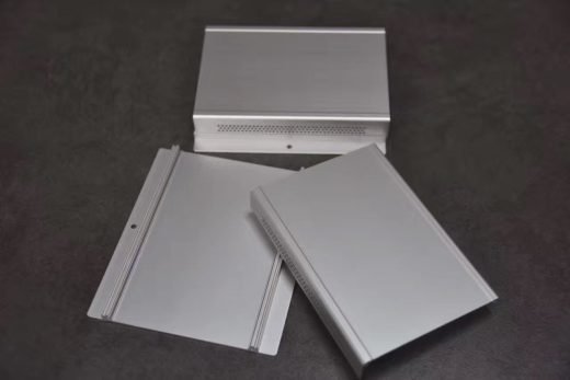
Prototyping orders are accepted from a single unit, and the minimum order quantity for production runs is 100 pieces. Cosmetic protection during machining uses custom soft-jaw fixtures, non-marring clamping pads and protective film, and finished parts travel individually wrapped in pearl cotton padding inside cartons to arrive undamaged.

 CNC Machining Parts