Custom EV Motor Cooling Enclosures | Extruded Aluminum Servo, Stepper & EV Motor Shells
Custom extruded aluminum motor housings with integral cooling fins. Tight bore roundness ≤0.05 mm. Black anodized, hard anodized. Cut, bored, drilled, tapped. Low die cost. 500 kg MOQ. Send drawings.
Technical Specifications
Certified precision data per ISO 9001:2015
Details
Certified precision data per ISO 9001:2015
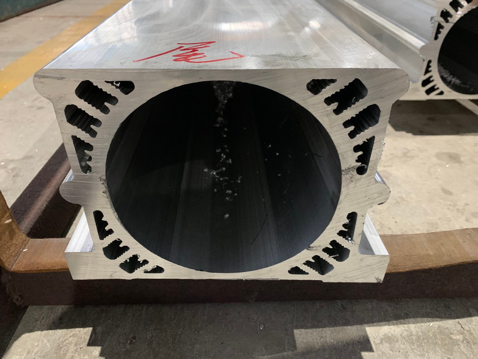
Extruded shells with integral fins. Round bores. Square ends. No die-cast tooling charges that kill your development budget.
If you’ve sourced motor housings before, you know the tradeoffs. Die casting gives you complex shapes but charges you eight weeks and a tooling bill that makes small production runs unworkable. Off-the-shelf extruded tube leaves you bolting on separate heat sinks and machining every feature from solid. Neither option is great when you’re trying to get a new motor design to market.
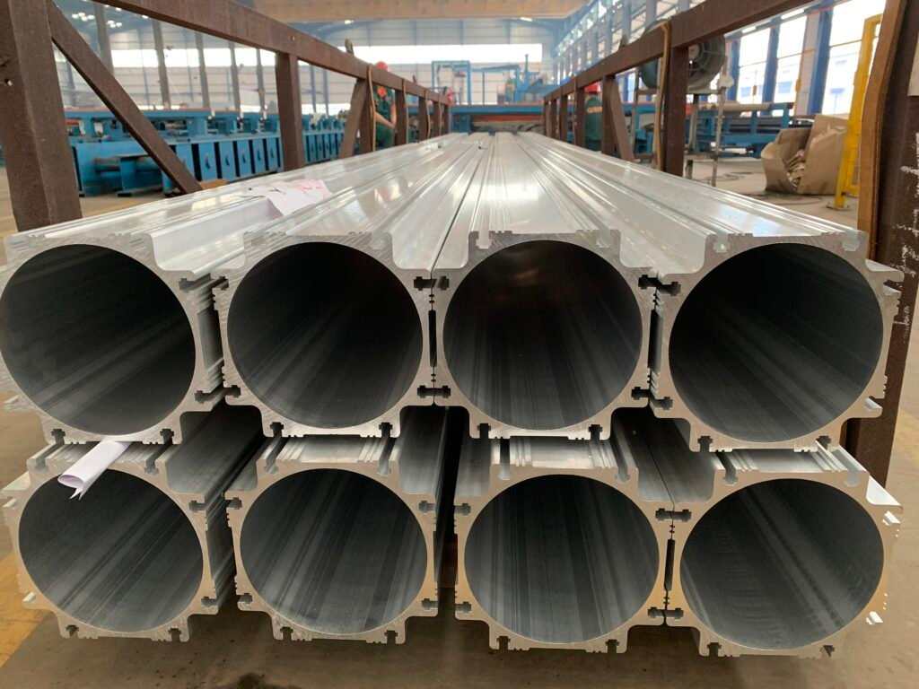
We extrude custom aluminum motor housings—round, square, or custom profile—with cooling fins formed in the same pass. You get a housing that’s optimized for your motor’s thermal load, with the inner bore and end faces machined to the tolerances your rotor and end bells demand.
Where Standard Motor Housings Fall Short (And How We Fix It)
The heat problem: fins that look the part but don’t perform
You run thermal simulations on a new motor design. The results say you need 40 mm tall fins with a 1.2 mm tip and 4 mm pitch. You send the drawing to three extrusion suppliers. Two say it’s impossible. The third gives it a try and delivers samples with half the fins underfilled, broken tips, and a scrap rate that makes production unworkable. You end up derating the motor or adding a fan—extra cost, extra noise, extra space.
This happens because tall, thin fins push against the physical limits of hot aluminum flowing through a die tongue. The die steel has to be thin enough to form the gap between fins, but strong enough to survive extrusion pressure at 500°C. When the ratio of fin height to fin thickness exceeds about 15:1, standard die design and standard die steel don’t hold up.
Our approach is to treat the thermal spec as a design input, not an afterthought. Before we cut steel, we assess the fin geometry against what’s actually extrudable in volume:
- Optimize within limits. Small changes to the root radius, tip taper, and wall transition can reduce die tongue stress by 20–30% while keeping the same total surface area. We’ll propose those changes, with numbers, so your thermal engineer can verify them.
- When direct extrusion can’t hit the numbers, we use skiving. We extrude a blank with thicker fins, then slice them down to the final thin profile on a CNC skiving machine. Achievable fin thickness: 0.2–0.4 mm. You get the thermal performance without asking the die to do the impossible.
- Die steel that lasts. The tongue sections are cut from H13 or SKD61 hot-work steel, vacuum hardened and triple tempered. We check tongue geometry every production shift. When wear approaches the tolerance limit, the die comes off the press for maintenance—before bad parts leave the line.
The noise problem: when the bore isn’t round, the motor whines
The housing arrives. You CNC-bore the inner diameter, press in the stator, assemble the end bells, and spin it up. The motor hums. Under load it whines. NVH measurements show a peak at twice the electrical frequency. The air gap between rotor and stator isn’t uniform—it varies around the circumference by 30 microns. The customer rejects the batch.
Root cause: the extruded blank didn’t have a uniform wall thickness around the bore. During cooling and straightening, the side with tall fins cooled faster than the smooth side, setting up residual stress. When you machined the bore, the stress released unevenly, and the roundness went out of spec. The extrusion was straight when it shipped, but the internal stress was waiting for a machine tool to unlock it.
Our approach tackles the problem at three stages:
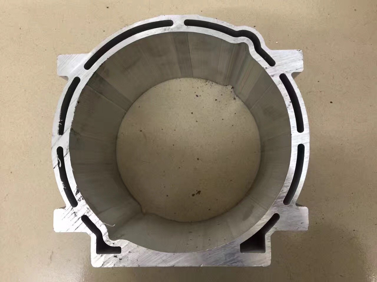
- Concentricity in the die. We design the die so the inner mandrel and outer die ring are precisely aligned, and we monitor wall thickness eccentricity during extrusion. For a typical motor housing, we hold wall variation within ±5% of nominal—not because the standard says so, but because we know what happens downstream when it drifts.
- Stress relief before machining. Every housing bar gets tension-stretched after extrusion (1–3% elongation). This pulls residual stress out of the profile before it ever reaches your machine shop. For high-precision applications—servo motors, spindle motors—we can add a thermal stress-relief cycle.
- Precision boring in-house if you want it. We’ll rough-bore, semi-finish, and finish-bore the inner diameter to ≤0.05 mm roundness as standard. Tighter specs (≤0.02 mm or better) are achievable with honing. We also machine the spigot register and end face in the same setup, so concentricity between the bearing seat and the stator bore is guaranteed by the machining sequence, not by luck.
The cost problem: die-cast tooling is too expensive, extrusion MOQs are too high
Developing a new motor. You need 200 housings for the pilot build. A die-cast supplier quotes eight weeks and $15,000 for the tool. An extrusion supplier says the minimum order is two tons. You don’t need two tons. You need 200 good housings, and you need them in four weeks.
Die casting has its place for complex, high-volume housings. But for tubular motor shells with external fins, extrusion tooling costs a fraction—often 80% less—and the die lead time is half. The catch is that many extrusion mills set their MOQ based on billet weight and production efficiency. They don’t want to run less than a ton. We’re set up differently.
- 500 kg MOQ on new dies. A typical motor housing weighs a few kilos per meter. Five hundred kilos gives you enough for a serious pilot run or a small production batch, without a warehouse full of dead stock.
- Tooling fee rebate. The die cost is charged upfront, but when cumulative orders reach a set volume, we refund it in full. If your motor goes into production, the tooling ends up free.
- Single-source from extrusion to finished housing. We handle the sawing, boring, spigot machining, drilling, and tapping. You don’t have to qualify two suppliers or argue about who’s responsible when the bore is out of spec. One drawing, one purchase order, one batch of finished housings.
What We Make
| Motor Type | Typical Housing | Material & Finish | What We Control |
|---|---|---|---|
| Servo motors | Round, medium fin density | 6063-T5, black anodized | Bore roundness ≤0.02 mm, precise spigot |
| Stepper motors | Small round or square | 6063-T5, black or natural anodized | Cost-effective, consistent slot geometry |
| EV traction motors | Large round, deep fins or water jacket | 6061-T6, powder coat or hard anodized | Corrosion resistance, weld integrity |
| Spindle motors | Round, balanced cross-section | 6063-T5, hard anodized | Electrical insulation, high rigidity |
| Industrial AC motors | Large diameter, moderate fins | 6063-T5, natural anodized or painted | Straightness, consistent wall thickness |
| Robot joint motors | Compact, custom profile | 6063-T5, black anodized | Light weight, tight tolerances in small envelope |
All cross-sections are extruded to your drawing. We don’t push standard dies when your design needs something different.
Alloy and Surface Finish Guide
6063-T5 is the standard for most motor housings. It extrudes well, anodizes evenly, and handles the thermal and mechanical loads of servos, steppers, and general industrial motors.
6061-T6 is for high-stress applications—large EV motors, motors that will be welded into a frame, or housings that double as structural members. It’s about 50% stronger than 6063-T5 and takes welding without losing significant strength in the heat-affected zone.
Surface finish affects thermal performance, corrosion resistance, and electrical safety:
| Finish | When to Use It | Why |
|---|---|---|
| Black anodized | Servo and stepper motors (industry standard) | Boosts radiation heat transfer 10–15%. Uniform matte black. Good electrical insulation |
| Hard anodized | Spindle motors, motors needing high dielectric strength | Thick, dense oxide layer. High voltage resistance. Very hard surface |
| Natural anodized (silver) | Cost-sensitive industrial motors | Lower cost, decent corrosion protection. Shows scratches less than black |
| Powder coated | Outdoor EV motors, marine-duty motors | Full encapsulation. Salt spray 1000+ hours. Wide color choice |
Tolerances That Matter for Motor Assembly
| Feature | Standard Capability | Tighter on Request |
|---|---|---|
| Bore roundness | ≤0.05 mm | ≤0.02 mm with honing |
| Bore surface finish | Ra 1.6 µm | Ra 0.8 µm or better |
| Spigot concentricity to bore | ≤0.03 mm | ≤0.01 mm |
| Cut length | ±0.10 mm | ±0.05 mm |
| End face squareness to bore axis | 0.05 mm per 100 mm diameter | 0.03 mm |
| Tapped holes | 6H class | 5H class |
Machining and Delivery Options
We ship motor housings three ways, depending on your in-house capabilities:
- Extruded blanks. Straightened, cut to rough length. You handle all machining. Lowest cost.
- Pre-machined blanks. Cut to finish length, rough-bored, ends faced square. Ready for your finish boring and spigot work. Good if you want to hold the final critical tolerances yourself.
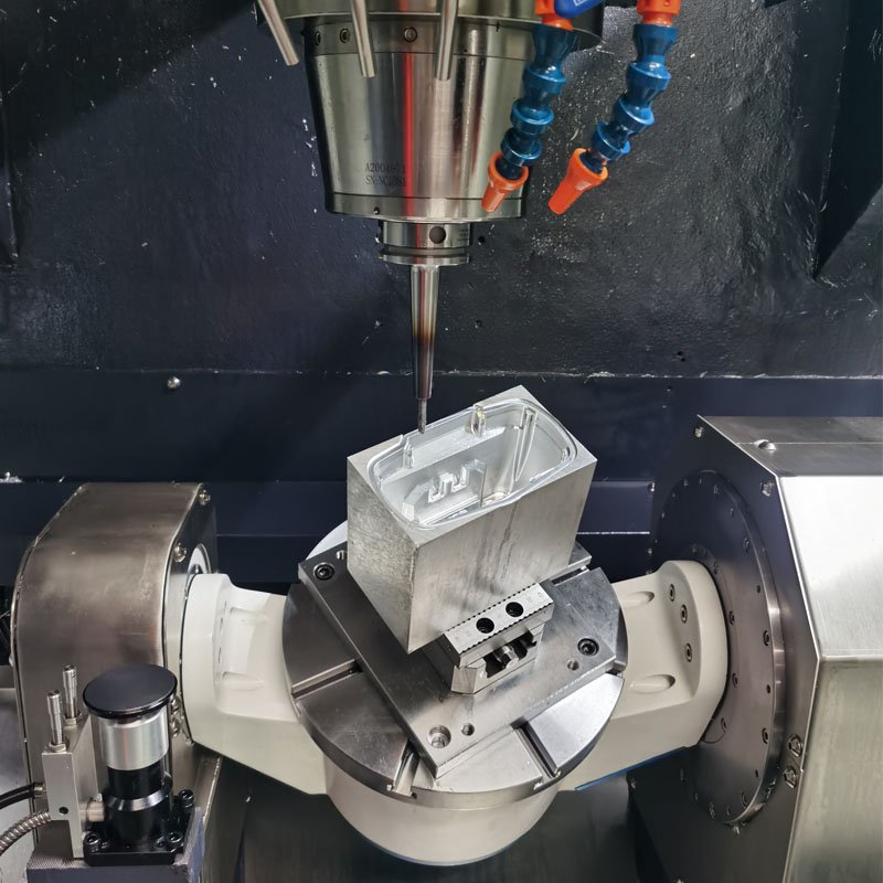
- Finished housings. Fully machined: precision bored, spigot and register faces cut, mounting holes drilled and tapped, cross-holes for cable glands, serial numbers engraved. Cleaned, deburred, and individually packed. You press in the stator and bolt on the end caps.
Frequently Asked Questions
Q1: We’re designing a new servo motor. Can you look at our thermal simulation and tell us if the fin design is extrudable?
Yes. This is the conversation we have most often. Send us the cross-section with fin dimensions or the thermal spec. We’ll assess it against our die strength models and tell you: (a) it works as drawn, (b) it works with these small changes, or (c) we recommend skiving for the fin tips. You’ll get a straight answer within 24 hours, not an optimistic “we’ll try” that turns into bad samples three weeks later.
Q2: We’re currently die-casting our motor housings. Can extrusion really replace that?
For tubular housings with external fins, extrusion is often the better process. Lower tooling cost, faster die changes, no porosity issues that show up as leaks or thermal hot spots. The tradeoff is that extrusion can’t do complex side bosses or deep undercuts the way die casting can. If your housing is basically a cylinder with fins, extrusion is almost certainly the right call. Send us the drawing and we’ll give you an honest comparison.
Q3: We had bore roundness problems with our last supplier. How do you guarantee it?
We guarantee roundness by controlling what causes it to go wrong: wall thickness eccentricity during extrusion, residual stress from cooling, and misalignment during machining. We stretch every bar after extrusion. For finished housings, we bore and cut the spigot in a single setup so the datums are machined in the same clamping. If you’re doing your own finish machining, we recommend a stress-relief heat treatment before boring—we can do that for you or supply the blanks already treated.
Q4: Do you do water-cooled motor housings with internal channels?
We can extrude straight cooling channels inside the housing wall—think longitudinal passages parallel to the bore. These work well for simple water jackets. For complex serpentine channels, a better approach is often to extrude the housing with a thicker wall and machine the cooling channels into it, then seal them with a welded or O-ringed outer sleeve. We’ve done both. Tell us your cooling requirement and we’ll propose the most practical route.
Q5: What’s the lead time for a prototype motor housing?
New die: 15–20 working days. Trial extrusion and sample machining: 3–5 days. Total time to a finished sample housing: roughly 20–25 working days. Rush orders can compress that—ask when you send the drawing.
Schematics
Cross-sectional dimensions
Related Profiles
Complementary hardware for your structural assembly
Aluminum Profile CNC Deep Processing Services: From Extrusions to Ready-to-Assemble Components
aluminum profile CNC deep processing, precision aluminum cutting and drilling, custom industrial aluminum components, aluminum extrusion post-processing factory, Linkedalu Metal…
Details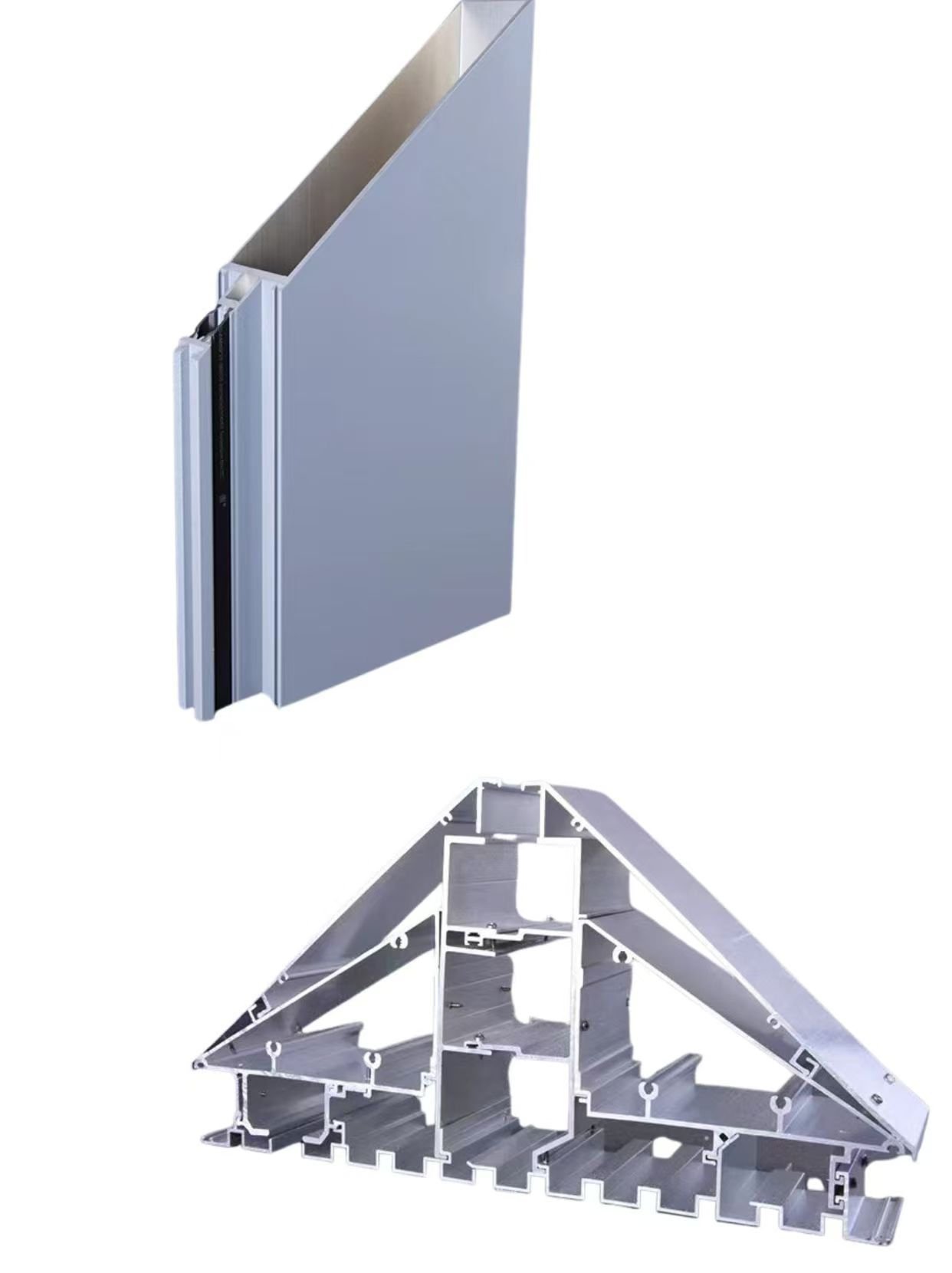
Architectural Aluminum Curtain Wall Profiles: Engineered Custom Framing Solutions
custom curtain wall aluminum profiles, architectural aluminum structural framing, 6063-T6 curtain wall extrusions, PVDF coated aluminum mullions, thermal break curtain…
Details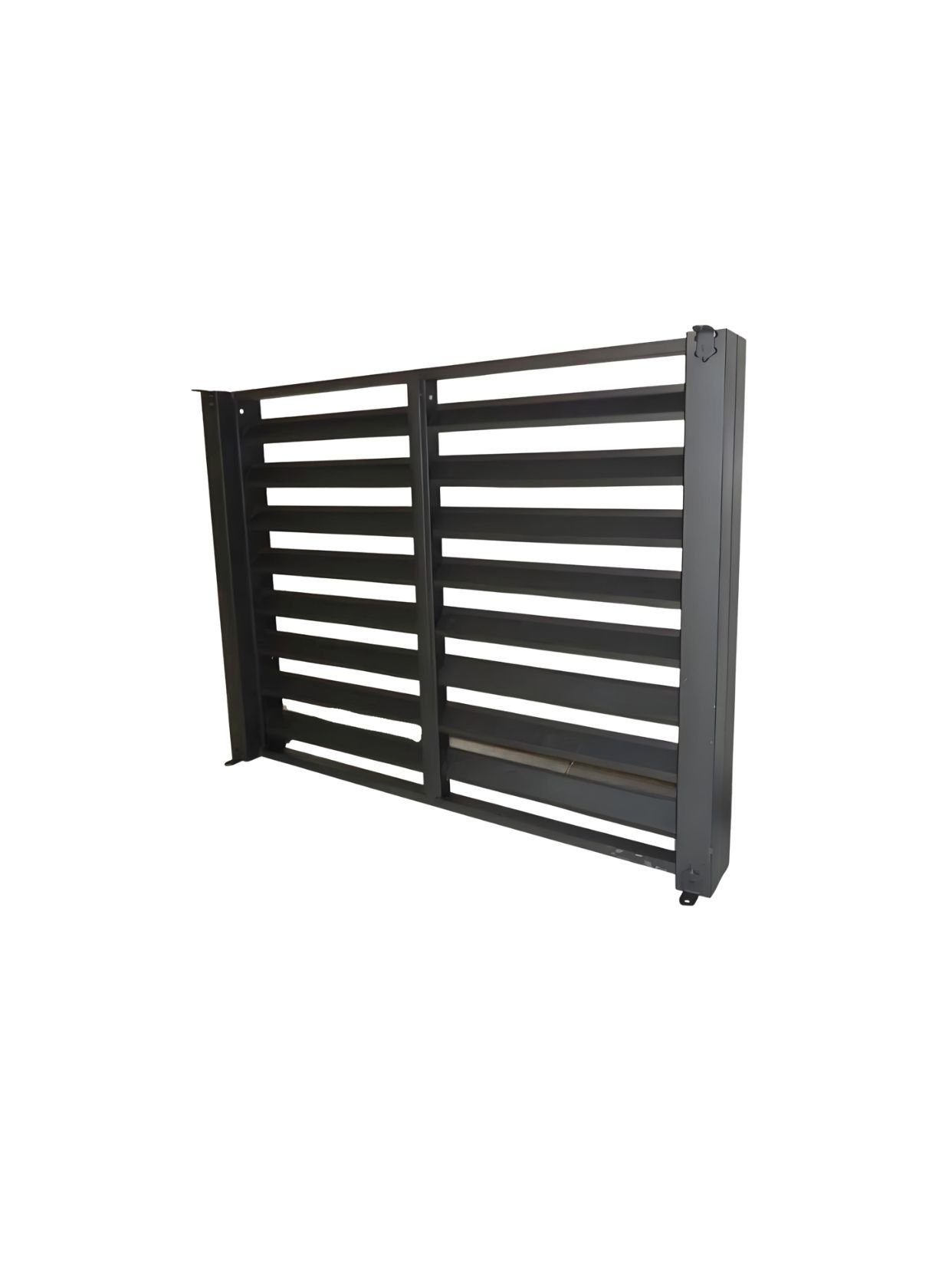
Custom Aluminum Louver Extrusion Profiles: High-Performance Architectural Sunshades & Facade Blades
Custom extruded aluminum louver profiles for building facades, sunshades, and ventilation systems. Z-blade, aerofoil, and C-blade designs in 6063-T5. Anodized,…
Details