Extruded Aluminum Heat Sinks for Power Electronics: Inverter, IGBT & EV Battery Cooling Design Guide
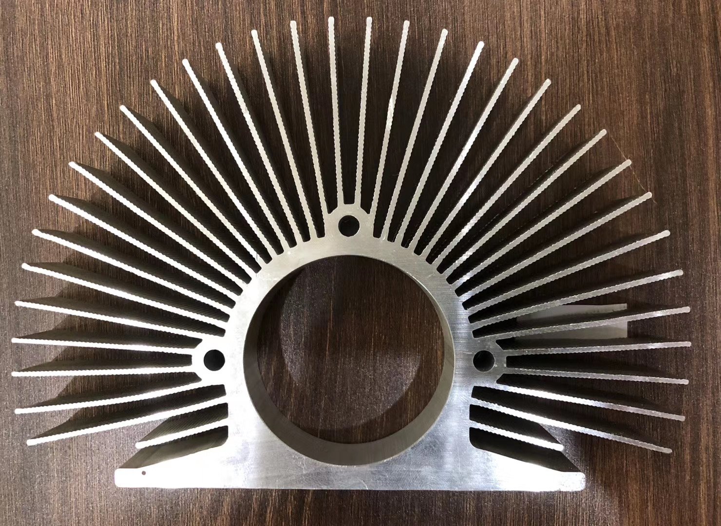
Designing power electronics cooling for inverters, IGBTs, or EV battery packs requires balancing thermal performance against the physical limits of an extrusion press. This engineering guide details alloy selection, fin geometry guidelines, CNC machining tolerances, and production parameters for custom aluminum heat sinks and liquid cold plates.
Technical Specifications
Certified precision data per ISO 9001:2015
Details
Certified precision data per ISO 9001:2015
Yes, aluminum extrusion handles power electronics cooling, from 10 kW string inverters to EV battery packs, but only when the profile is designed around the physics of heat and the limits of the extrusion press. The right approach depends on what you are cooling: a passive IGBT heatsink, a solar inverter housing, or a liquid-cooled battery cold plate. This page walks through the design methodology, alloy selection, and real production parameters we use at our extrusion factory, so you can specify a profile that performs and manufactures without surprises.
How to Design an Aluminum Extrusion Heat Sink
Heat sink design starts with thermal requirements, not geometry. You need three numbers before anyone cuts die steel: total heat load in watts, maximum ambient temperature, and the allowable junction temperature. Everything else, fin count, fin height, base thickness, alloy, flows from those three.
Here is the workflow we follow with customers:
- Thermal specification. You give us heat load (W), ambient temp (°C), max junction temp (°C), and cooling mode (natural convection, forced air, or liquid). If you have a CFD model, send it. If not, tell us the power and we will work backward.
- Fin geometry calculation. Based on heat load and cooling mode, we calculate the required surface area. Natural convection needs more surface area and taller fins. Forced air allows denser, shorter fins. The fin height-to-gap ratio matters more than fin count alone.
- Extrudability check. We evaluate your proposed cross-section against what 6063-T5 can do at production speed. The two numbers that kill more designs than any other are tongue ratio and circumscribing circle.
- Die design and correction. If the profile passes, our die engineers design the tooling, accounting for metal flow, die deflection, and thermal expansion. We flag any section that will not fill properly before the die is built.
- Sample extrusion and thermal validation. First-off samples go to you for thermal testing. Adjustments to fin geometry or surface treatment happen here, not in production.
Two Numbers That Determine If Your Design Is Extrudable
Most heat sink designs that fail at the extrusion stage fail because of the same two parameters. If you check these before sending a drawing, you will save weeks.
| Parameter | What It Means | Practical Limit (6063-T5) | Why It Matters |
|---|---|---|---|
| Tongue ratio | Fin gap depth ÷ fin gap width. The die tongue is the thin steel finger between two fins. If the ratio is too high, the tongue bends or breaks under extrusion pressure. | Below 3:1 is safe. Above 5:1 is risky. Above 7:1, the die will not survive production. | This is the single most common reason a heat sink profile cannot be extruded as drawn. |
| Circumscribing circle | The smallest circle that encloses the entire profile cross-section. Determines which press can run it. | Up to 250 mm on an 1800-ton press. Up to 350 mm on a 2500-ton press. | Profile wider than your supplier’s press can run, the profile cannot be made there, period. |
| Extrusion ratio | Billet cross-section area ÷ profile cross-section area. Determines press force and speed. | 30:1 to 60:1 for heat sinks. Below 20:1, metal flows poorly. Above 80:1, speed drops and die wear increases. | Affects surface quality, dimensional consistency, and production cost. |
Fin Geometry Guidelines
Fin design is a trade-off between surface area and manufacturability. Here is what works in production:
| Parameter | Comfortable Range | Pushing the Limit | Notes |
|---|---|---|---|
| Fin pitch | ≥ 3 mm | 1.5 mm (short fins only) | Tighter pitch needs shorter fins to keep tongue ratio safe. |
| Fin height | Up to 50 mm | 80 mm (with draft angle 0.5°–1.0°) | Fins taller than 50 mm need a slight draft or the die tongue fails. |
| Fin tip thickness | ≥ 0.5 mm as-extruded | 0.2 mm via skiving | Skiving produces thinner tips but adds a secondary process. |
| Base thickness | 2–20 mm | Thicker by design | IGBT modules typically need 8–15 mm bases. |
| Profile width | 10–300 mm | Up to 420 mm on large press | Wider profiles cost more per kilogram due to press time. |
When to Specify Which Tolerances
Standard extrusion tolerances (per EN 755-9 or ANSI H35.2) cover most of a heat sink profile. But two surfaces usually need tighter control than extrusion alone can deliver, and those are the ones you should call out explicitly on the drawing:
- Mounting face flatness. As-extruded: roughly 0.2 mm per 100 mm. CNC-milled: 0.05 mm or better. Specify the milled flatness on the drawing if the surface contacts a semiconductor or thermal interface material.
- Fin-to-fin spacing. As-extruded: ±0.15 mm typical. If your fan shroud requires tighter spacing to prevent bypass, specify it and we will hold it with die correction, not secondary machining.
- Hole position. Drill and tap after extrusion. Do not rely on extruded feature positions for precision hole locations.
Can Aluminum Extrusion Be Used for Inverter Cooling?
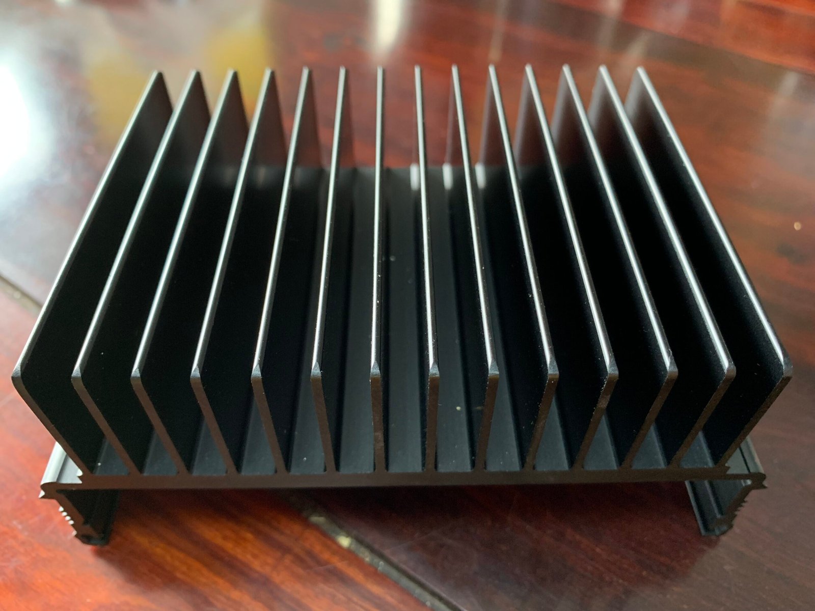
Yes. Extruded aluminum heatsinks are the standard cooling solution for solar string inverters (10–50 kW), central inverters, UPS systems, and variable frequency drives. The extrusion process produces a one-piece fin-and-base structure with no thermal interface resistance between fins and base, which is why it outperforms assembled or bonded heatsinks in continuous-duty applications.
What changes between inverter types is the profile size, base thickness, and secondary machining. Here is how the design shifts by application:
Solar String Inverters (10–50 kW)
These use medium-width profiles (120–250 mm) with moderate fin height (25–40 mm) and a base thickness of 6–10 mm. The heatsink often doubles as the enclosure sidewall, so the profile includes integral mounting features for PCB standoffs and cable glands. Most string inverter heatsinks we produce are 6063-T5, black anodized for outdoor emissivity, with CNC-drilled M4–M6 mounting holes.
Typical thermal load: 150–400 W dissipated from the IGBT and filter components. Forced air via internal fans is standard.
Industrial VFDs and UPS Systems
Variable frequency drives and UPS systems tend toward wider profiles (200–300 mm) with thicker bases (10–15 mm) because they mount multiple IGBT modules on a single heatsink. The base must stay flat under bolt preload from 4–8 modules, each torqued to 3–5 N·m. That is why base flatness of 0.05 mm matters here: any gap between module and heatsink adds thermal resistance that compounds across modules.
Power dissipation per module: 50–150 W. Total heatsink dissipation: 200–800 W depending on drive rating.
IGBT Module Mounting: What the Base Needs to Do
The mounting face of an inverter heatsink has one job: maintain flat, continuous contact with the IGBT baseplate so thermal compound can do its work. Here is what that requires in practice:
| Requirement | Specification | Why |
|---|---|---|
| Base thickness | 8–15 mm | Resists flex under module bolt preload (3–5 N·m per bolt, 4–8 bolts per module). |
| Surface flatness | ≤ 0.05 mm | Ensures thermal paste layer stays thin and uniform. Every 0.01 mm of extra gap adds roughly 0.5–1.0 K of thermal resistance. |
| Surface roughness | Ra 1.6 µm or finer | Smooth surfaces let thermal paste spread evenly without pooling. |
| Flatness method | CNC face milling after extrusion | As-extruded flatness (0.2 mm/100 mm) is not good enough for IGBT mounting. |
Heat Pipe Integration for Hotspot Management
Some inverter designs concentrate heat at specific locations rather than spreading it evenly. In those cases, we can extrude a semi-circular groove into the base for a heat pipe (common diameters: 6 mm, 8 mm, 10 mm). The groove is formed in the same extrusion pass, so there is no added process step. The heat pipe is pressed in after machining, with thermal epoxy filling any gap.
This works well for designs where one IGBT module runs hotter than the others, or where the control board generates a localized hotspot away from the main fin array.
Can Aluminum Extrusion Be Used for EV Battery Cooling?
Yes, and it is one of the fastest-growing applications for custom extrusion. There are two approaches, and they serve different pack architectures:
Approach 1: Extruded Liquid Cold Plate with Internal Channels
This is the direct method. We use a porthole die to form closed or semi-closed internal channels inside a flat extrusion during a single pass. The coolant (typically 50% ethylene glycol and water) flows through these channels and removes heat by conduction through the aluminum wall.
This approach replaces multi-part brazed or tube-in-plate assemblies with a one-piece extrusion. The result is fewer joints, lower leak risk, and 30–50% less assembly labor compared to tubular cold plates.
Key design parameters for extruded cold plates:
| Parameter | Typical Range | Notes |
|---|---|---|
| Channel diameter | 3–8 mm | Smaller channels give more surface area per unit volume but increase pressure drop. |
| Wall between channels | ≥ 3 mm | Below 3 mm, the wall cannot reliably hold pressure during extrusion or in service. |
| Operating pressure | 0.5–1.5 MPa | EV coolant loops typically run at 0.3–0.8 MPa with a 2x safety margin. |
| Burst pressure | ≥ 3.0 MPa | Validated in pressure testing before shipment. |
| Leak test | 250 kPa, 60 s, < 30 Pa leak | Every cold plate is pressure-tested before it ships. |
| Coolant | 50% glycol-water | Flow rate 0.5–2.0 L/min per module. |
How the Channels Get Sealed
Extrusion forms the internal channels in a continuous length. The ends are open. To make a functional cold plate, the ends must be sealed and inlet/outlet ports added. Three methods, depending on the design:
- Friction stir welding (FSW). The default for EV cold plates. A rotating tool plunges into the aluminum at the channel ends, friction heats and stirs the metal into a solid-state bond. No porosity, no filler material, withstands thermal cycling. This is the same process Tesla and CATI use on battery packs.
- Laser welding. Used when the end geometry is complex or access is limited. Slightly lower strength than FSW but more flexible for non-flat surfaces.
- Machined end caps with O-rings. For serviceable cold plates where the channel may need to be opened. Less common in production EV packs but useful for prototyping.
Approach 2: Extruded Battery Frame with Separate Cooling
Not every EV pack cools through a dedicated cold plate. Some architectures use extruded aluminum frames or trays that provide structural support for the cell modules, with cooling plates bonded or bolted to the frame separately. In these designs, the extrusion is structural first and thermal second.
For structural battery frames, the alloy shifts:
| Component | Typical Alloy | Why |
|---|---|---|
| Cold plate (liquid cooling) | 6063-T5 | Higher thermal conductivity (~200 W/m·K). Non-structural, bolted inside the pack. |
| Battery tray / frame | 6061-T6 | Higher yield strength (276 MPa vs 145 MPa). Carries cell weight, survives crash loads. |
| Side rails / cross members | 6005A-T6 | Good weldability for frame assembly. Moderate strength, good extrudability. |
This split is common in production EV packs. Using 6063 for the cooling plate gives you 20% better thermal conductivity than 6061. Using 6061 for the frame gives you almost double the strength. Trying to do both with one alloy means compromising on one.
CFD Validation Before Die Cutting
Before we cut die steel for a cold plate, we run CFD analysis on the proposed channel layout. The simulation checks for three things:
- Flow distribution. Are all channels receiving equal flow, or are some starved? Uneven flow means uneven cooling, which means some cells run hotter than others.
- Pressure drop. Does the channel layout create excessive backpressure? If the pump has to work too hard, energy efficiency drops and the coolant pump becomes a bottleneck.
- Thermal uniformity. Is the temperature gradient across the plate acceptable? For lithium-ion cells, the ideal is under 5°C difference between the hottest and coldest point on the plate.
If the simulation shows a 20% flow imbalance between channel legs, we adjust the channel diameters or add flow restrictors in the die design. This costs nothing at the design stage and saves a failed production run later.
Technical Specifications
| Parameter | Specification |
|---|---|
| Alloy | 6063-T5 (standard for heatsinks), 6061-T6 (structural / high pressure), 6005A-T6 (welded frames) |
| Thermal conductivity | 6063-T5: ~200 W/m·K | 6061-T6: ~167 W/m·K |
| Yield strength | 6063-T5: 145 MPa | 6061-T6: 276 MPa |
| Max continuous service temp | 6063-T5: ~200°C | 6061-T6: ~250°C |
| Tolerance standard | EN 755-9 (EU), DIN 1748 (legacy DE) |
| Profile width | 10–300 mm (standard), up to 420 mm on large press |
| Fin height | Up to 50 mm standard, 80 mm with die design |
| Fin pitch | ≥ 2.5 mm standard, 1.5 mm minimum |
| Base thickness | 2–20 mm (8–15 mm for IGBT mounting) |
| Mounting surface flatness | ≤ 0.05 mm (CNC milled) |
| Surface finish | Mill finish, black anodized (emissivity 0.85–0.90), hard anodized, sandblasted |
| Anodizing thickness | 10–25 µm (per Qualanod standards) |
| Internal channel diameter (cold plates) | 3–8 mm |
| Cold plate operating pressure | 0.5–1.5 MPa (burst ≥ 3.0 MPa) |
| Leak test | 250 kPa, 60 s, < 30 Pa leakage |
| Standard length | 6 m extruded, cut-to-length from 100 mm |
| MOQ (new die) | 300 kg |
| Typical die cost | $800–$5,000 depending on complexity |
| Lead time (new die, first sample) | 10–15 working days |
| Lead time (repeat order) | 7–10 working days |
| Quality certification | ISO 9001:2015 |
Application Scenarios
Solar Inverters
String inverter heatsinks (10–50 kW) with integrated enclosure features. 6063-T5, black anodized for outdoor UV resistance and thermal radiation. Base thickness 6–10 mm, profile width 120–250 mm. CNC-drilled mounting holes for IGBT modules and terminal blocks. Typical heat dissipation: 150–400 W per unit.
EV Battery Cooling
Extruded liquid cold plates with internal serpentine or parallel channels. 6063-T5 for conductivity, sealed with FSW. Channel diameter 3–6 mm, wall thickness ≥ 3 mm. Pressure-tested to 250 kPa. CFD-validated flow distribution. Coolant: 50% glycol-water at 0.5–2.0 L/min. Used in battery packs from 40–150 kWh.
IGBT Power Modules
Heavy-duty heatsink profiles for traction inverters, motor drives, and welding equipment. 6063-T5 with CNC-milled mounting face flatness ≤ 0.05 mm. Base thickness 8–15 mm to resist flex under bolt preload. Optional heat pipe grooves for hotspot management. Profile width 150–300 mm.
UPS and VFD Systems
Multi-module mounting profiles for uninterruptible power supplies and variable frequency drives. 6061-T6 for structural bases carrying 4–8 IGBT modules. Wider profiles (200–300 mm), thicker bases (10–15 mm). CNC machining for flat mounting surfaces, threaded holes, and thermal via patterns.
Energy Storage Systems
Battery rack frames and cooling plates for grid-scale energy storage. 6061-T6 structural frames with 6005A cross members, 6063-T5 cold plates bolted inside. Designed for 10+ years of thermal cycling. Vibration-tested per UN 38.3 for transport.
Frequently Asked Questions (FAQ)
Q1: What is the maximum profile width for an IGBT heat sink extrusion?
On our 1800-ton press, the standard maximum profile width is 300 mm. Wider profiles up to 420 mm are possible on the 2500-ton press, but die cost and minimum order quantity increase. Most IGBT modules (62 mm, 130 mm, 140 mm bolt patterns) fit comfortably within 300 mm.
Q2: Can you extrude internal liquid cooling channels for battery cold plates?
Yes. We use a porthole die to form closed or semi-closed channels inside the profile during a single extrusion pass. Channel diameters range from 3 to 8 mm. The ends are sealed with friction stir welding (FSW) or laser welding, then pressure-tested at 250 kPa with a leakage threshold below 30 Pa over 60 seconds.
Q3: Should I use 6061 or 6063 for an extruded battery cold plate?
6061-T6 if the cold plate is structural (carries cell load or bolts into the pack frame) or needs to hold pressure above 1 MPa. Its yield strength is 276 MPa versus 6063’s 145 MPa. 6063-T5 if thermal conductivity matters more than strength and pressures stay under 1 MPa. 6063 conducts roughly 200 W/m·K versus 6061’s 167 W/m·K. Many EV packs use 6063 for the cold plate and 6061 for the structural frame.
Q4: How are the ends of extruded cooling channels sealed?
Three methods depending on the design: friction stir welding (FSW) for high-strength, leak-free seals on flat surfaces; laser welding for complex geometries; and machined end caps with O-ring grooves for serviceable connections. FSW is the default for EV battery cold plates because it produces no porosity and withstands thermal cycling.
Q5: What pressure can an extruded aluminum cold plate withstand?
Typical operating pressure is 0.5 to 1.5 MPa. Burst pressure exceeds 3.0 MPa in validated tests. Wall thickness between channels should be at least 3 mm to maintain these pressures. Every cold plate is leak-tested at 250 kPa before shipping.
Q6: What tolerance standard applies to extruded heat sink profiles?
EN 755-9 for the European market and ANSI H35.2 for North America. DIN 1748 is the older German standard, still referenced on some legacy drawings. For heat sinks, the critical tolerances are profile width (±0.3 mm typical), wall thickness (±0.15 mm), and straightness (±1 mm per meter, or tighter with roller straightening). Mounting surfaces are CNC-milled after extrusion to achieve flatness of 0.05 mm or better, which standard extrusion tolerances cannot guarantee.
Q7: Can you run CFD simulation on the flow channels before cutting the die?
Yes. Before die steel is cut, we run CFD analysis on the proposed channel layout to check flow distribution, pressure drop, and thermal uniformity. This typically catches dead zones and uneven flow patterns early. If a serpentine channel shows 20% flow imbalance between legs, we adjust channel diameters or add flow restrictors in the die design.
Q8: How thick should the base be under an IGBT module?
8 to 15 mm is the practical range for IGBT mounting bases. Thinner than 8 mm and the base flexes under bolt preload, breaking thermal interface continuity. Thicker than 15 mm adds weight and cost with diminishing thermal returns. The mounting face must be CNC-milled flat to 0.05 mm or better after extrusion, because as-extruded flatness runs around 0.2 mm per 100 mm.
Send Us Your Thermal Spec or Drawing
If you have a thermal requirement, a 3D drawing, or even a sketch with fin dimensions and heat load, send it over. Our die engineers will check it against extrudability limits and tell you what works, what does not, and what we would change. No cost, no obligation. You get a manufacturability report and a quote within two working days.
Technical Review: Linkedalu Engineering Team Update: 21st Aug.2026
Email: sales@linkedalu.com | WhatsApp: +86 18965152501
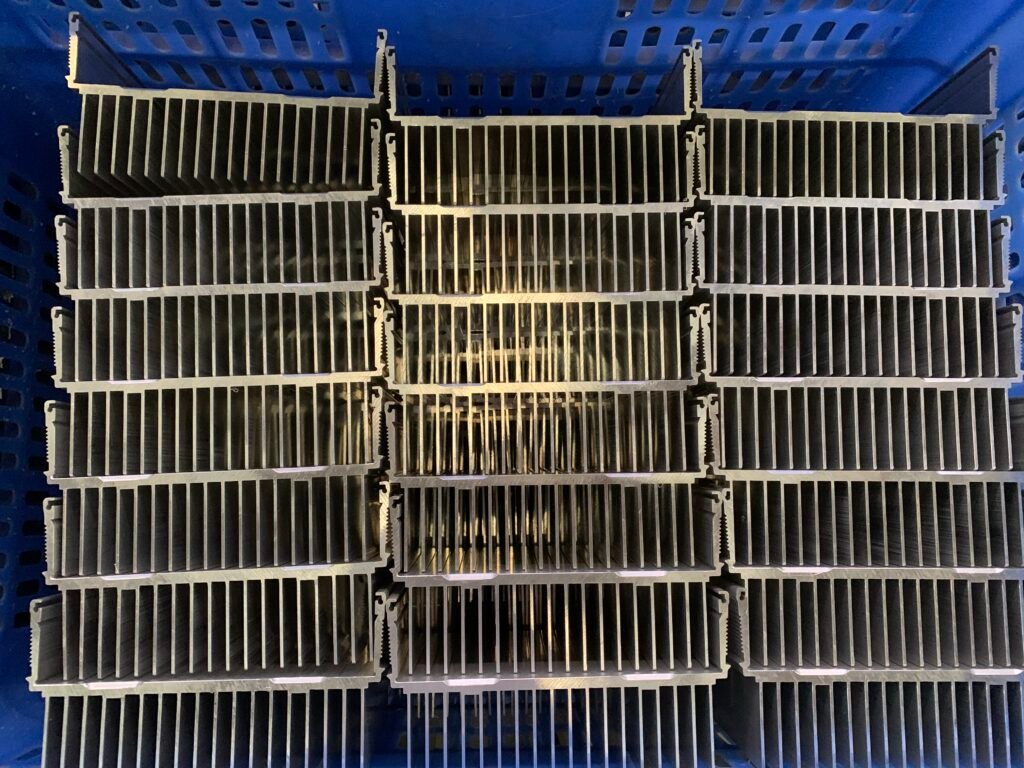
Schematics
Cross-sectional dimensions
Related Profiles
Complementary hardware for your structural assembly
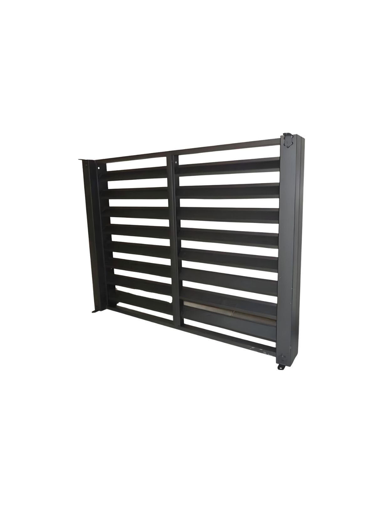
Custom Aluminum Louver Extrusion Profiles: High-Performance Architectural Sunshades & Facade Blades
Custom extruded aluminum louver profiles for building facades, sunshades, and ventilation systems. Z-blade, aerofoil, and C-blade designs in 6063-T5. Anodized,…
Details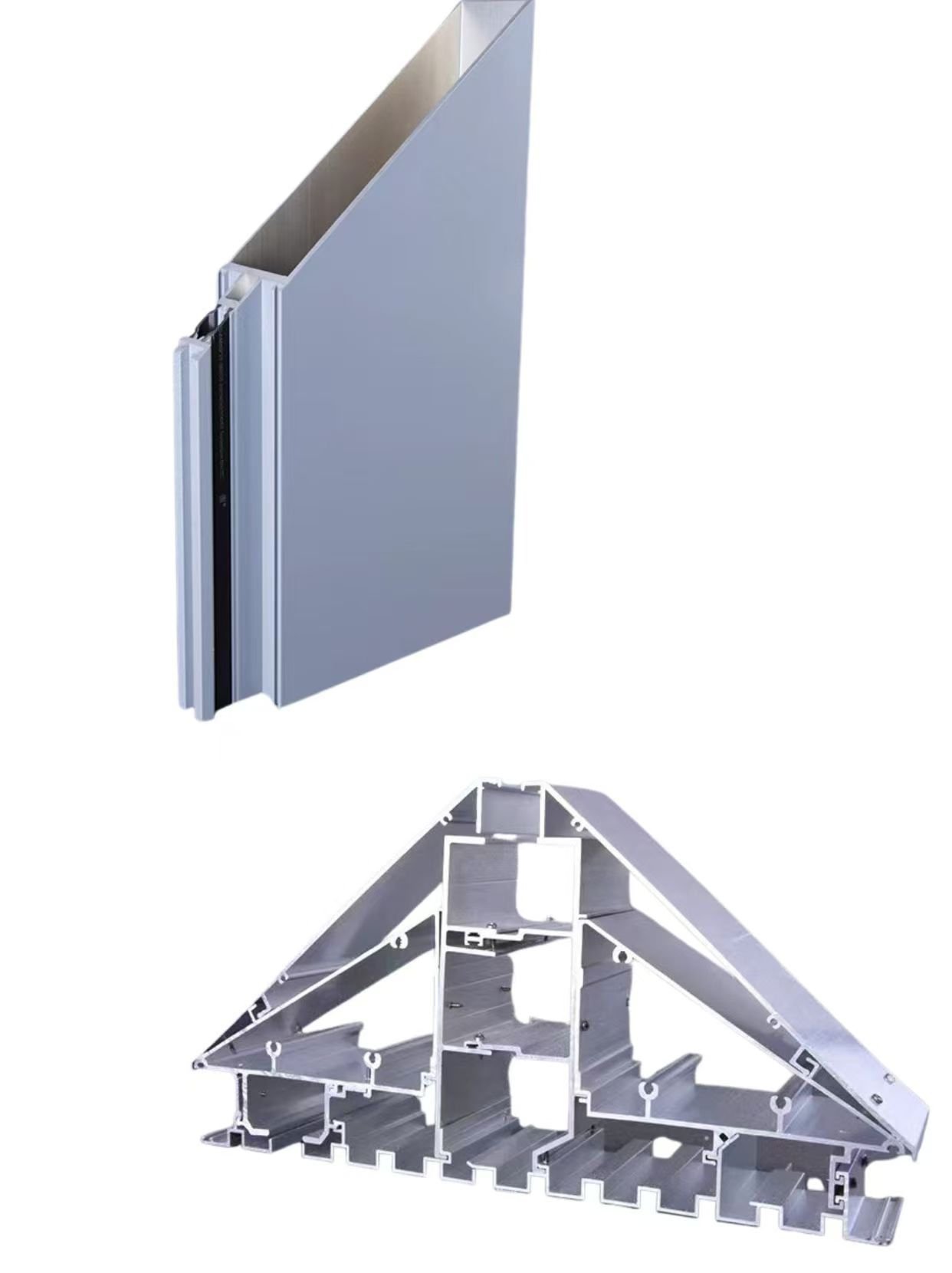
Architectural Aluminum Curtain Wall Profiles: Engineered Custom Framing Solutions
custom curtain wall aluminum profiles, architectural aluminum structural framing, 6063-T6 curtain wall extrusions, PVDF coated aluminum mullions, thermal break curtain…
Details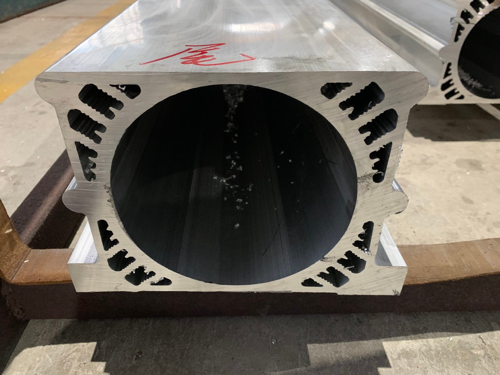
Custom EV Motor Cooling Enclosures | Extruded Aluminum Servo, Stepper & EV Motor Shells
Custom extruded aluminum motor housings with integral cooling fins. Tight bore roundness ≤0.05 mm. Black anodized, hard anodized. Cut, bored,…
Details