Robot & AI Automation Aluminum Parts | CNC Machined Components for Robotics
CNC machined aluminum parts for robots, AGVs, linear actuators, and AI vision systems. Joint housings, base plates, camera frames. Thin-wall, tight tolerance. 6061-T6, anodized. Low volumes welcome.
Technical Specifications
Certified precision data per ISO 9001:2015
Details
Certified precision data per ISO 9001:2015
Robot arms move. AGVs carry loads. Vision systems inspect at micron-level accuracy. The aluminum parts in these machines don’t just sit there—they’re under stress, in motion, and they define how precise the whole system can be. We machine those parts.
If you’re designing a collaborative robot, an autonomous guided vehicle, or an AI-powered inspection station, the aluminum components in your BOM probably share a few things in common. They’re not off-the-shelf. They have thin walls, tight bores, and multiple faces that all need to be square to each other. And you don’t need ten thousand of them—you need fifty this month, maybe a hundred next quarter when the design settles down.
That’s the work we do. Send us the STEP file. We’ll machine it, anodize it, and ship it.
What We Machine (And Why These Parts Are Tricky)
Robot Arm Joint Housings and Connecting Arms
These are the shells and structural links that form the skeleton of a collaborative robot or industrial arm. They’re usually cylindrical or box-shaped, with bearing bores at both ends and mounting flanges on the sides.
The problem every machinist runs into: the wall is thin—sometimes 3 mm or less—and as soon as you clamp it for boring, it goes slightly oval. You finish the bore, release the clamp, and the hole springs back out of round. The bearing doesn’t seat properly. The joint has play from day one.
We use pie-shaped soft jaws or expanding mandrels that spread the clamping force evenly around the circumference. The part is held securely without being squeezed out of shape. Bearing bores at both ends get finish-bored in one setup on a 4-axis machine, so the coaxiality between them is controlled by the machine’s own alignment, not by re-fixturing. For the mounting flange faces, we mill them flat in the same setup so they’re perpendicular to the bore axis. That’s what keeps a robot arm from wobbling at full reach.
Material is usually 6061-T6. Strong enough, machines cleanly, anodizes well.
Linear Actuator Base Plates
Every automated production line has linear modules—ball-screw or belt-driven stages that move tooling from station to station. The base plate is the long aluminum plate that everything bolts to. The linear rail on top. The bearing blocks. The motor mount at one end.
Here’s the thing about a 1.5-meter base plate: it moves. Not during machining—after. You mill it flat, you hit the tolerance, you ship it. Three weeks later the customer calls and says the rail is rocking. What happened? The plate was full of residual stress from the aluminum mill. Roughing cuts released some of it. The rest came out slowly over time, and the plate bowed by 0.1 mm. On a precision linear stage, that’s enough to cause binding.
We rough-machine the plate, then send it for a thermal stress-relief cycle. After that, we do the finish machining. The rail mounting surface and the bearing housing seats get milled in one setup. We check flatness with a granite surface plate and a dial indicator. For a 1.5-meter plate, we hold 0.05 mm flatness. The threaded holes for the rail bolts are thread-milled, not tapped, so they’re exactly on position and perpendicular to the mounting surface. A crooked bolt in a linear rail is a problem waiting to happen.
AI Vision System Camera Frames and Mounting Brackets
Machine vision is everywhere now—quality inspection, pick-and-place, autonomous navigation. The cameras and lights are mounted on aluminum frames that position them at precise angles and distances from the target. If the camera mount is off by 0.2 mm, the entire calibration is off.
These frames often have multiple mounting faces at different angles. One face holds the camera, another holds the ring light, a third bolts to the gantry. All the relationships need to be right.
We machine these on a 3/4/5-axis CNC so we can reach multiple faces without breaking the setup. All the critical mounting holes are machined from the same datum, so their positions relative to each other are controlled by the machine’s positioning accuracy—not by how carefully we re-clamped the part. Cable routing slots get milled into the frame body. Edges get deburred so they don’t cut wires.
We also do the anodizing in-house. Black anodized frames are common for vision systems because they reduce stray reflections. Silver is standard when the part is inside an enclosure and appearance matters less.
AGV / AMR Chassis Plates and Structural Parts
Autonomous mobile robots(AMRs)—the ones moving materials around warehouses and factories—run on aluminum chassis. The base plate, the top deck, the side panels, the battery compartment frame. These are big, flat, and full of holes.
A typical AGV base plate might be 1200 mm by 800 mm, with mounting patterns for drive wheels, casters, lift mechanisms, and sensor brackets. If the plate is bowed, the whole vehicle tracks crooked. If the hole pattern for the drive unit is off, the wheels don’t align and the tires wear unevenly.
We use a vacuum table to hold large plates flat during machining. No clamps distorting the edges. All hole patterns are programmed from a single reference corner, so the drive unit holes, caster holes, and sensor bracket holes all relate back to the same origin. No accumulated error. For battery compartments, we machine flat mounting surfaces and add ventilation slots if the design calls for them.
Material is 6061-T6 for most AGV parts. Good stiffness-to-weight ratio, welds acceptably if the chassis needs welded joints.
Sensor Brackets and Precision Alignment Fixtures
These are the small, precise parts that hold sensors, cameras, and alignment tools in place on an automated line. A laser distance sensor needs its bracket to hold it at exactly the right height and angle. A proximity switch needs its mounting hole to be dead center on the target path.
The parts are small—maybe 50 mm by 30 mm by 20 mm—but the tolerances are tight. A dowel pin hole might be 6H7, which means a few microns of clearance. Get it wrong, and the pin either won’t go in or falls out.
We batch-machine small parts on the CNC with multiple workholding stations. Once the program is proven on the first piece, the rest come out identical. Dowel holes are finish-reamed, not just drilled. Threads are milled for consistency. We keep the program on file, so when you reorder the same bracket six months later, you get the same part.
What We Do Differently
We’re set up for the quantities robot companies actually order.
Robot and AI startups iterate fast. One month it’s 20 prototype parts. Six months later it’s 200 production units. We handle both. No minimum order threshold that forces you to buy more than you need. No price penalty for small batches. CNC doesn’t care if you want 5 or 500—the setup is the setup.
We’ll tell you if something in your drawing looks off.
If your wall thickness is 1 mm and the part is 200 mm long, it’s going to vibrate during machining and the surface finish will suffer. If you’ve put an M4 threaded hole 2 mm from an edge, it’s going to bulge or crack. Our engineers flag these things during CAM review, before chips are made. It’s not criticism—it’s the kind of feedback that saves you from getting parts you can’t use.
Anodizing happens under our roof.
After machining, robot parts usually need surface treatment. We do anodizing and hard anodizing in-house. Your parts don’t leave the building between CNC and finishing. That means one team is responsible for the entire process. If something goes wrong, there’s no finger-pointing between a machine shop and a plating house. We own it all.
Tolerances We Hit Every Day
These aren’t theoretical limits from a machine catalog. These are the numbers we put on inspection reports.
| Feature | What We Hold | How We Check It |
|---|---|---|
| Bearing bore diameter | H7 tolerance (+0.015/0 mm on Ø30) | Bore gauge calibrated to ring standard |
| Bore coaxiality | ≤0.02 mm between two bearing seats | CMM or test bar with dial indicator |
| Flatness on rail mounting surface | 0.05 mm over 1500 mm | Granite surface plate + dial indicator |
| Hole position | ±0.05 mm from datum | CMM or height gauge |
| Thread quality | 6H class, no tear-out | Go/no-go thread gauge |
| Surface finish on sealing faces | Ra 0.8–1.6 µm | Surface roughness tester |
Materials We Stock
| Alloy | When We Use It | Why |
|---|---|---|
| 6061-T6 | General robotics, AGV parts, brackets | Best all-rounder. Strong, machines well, anodizes cleanly |
| 7075-T6 | High-stress robot arm links, thin-wall structural parts | Almost as strong as mild steel. More expensive, harder on tools |
| 6063-T5 | Enclosure parts, cosmetic covers | Softer, better for complex profiles that need bending or anodizing |
| MIC-6 cast plate | Flatness-critical parts, vision bases | Cast aluminum plate, stress-relieved, extremely stable |
FAQ
Q1: We’ve had issues with aluminum threads stripping in robot arm parts that get assembled and disassembled repeatedly. What do you recommend?
A: Two approaches, often used together. First, we thread-mill instead of tapping. A milled thread has a smoother surface finish and better dimensional control than a tapped one, so the bolt engages more evenly. Second, for holes that see frequent assembly, we install stainless steel Helicoil inserts. The insert becomes the wear surface, and the aluminum body just holds the insert. If a thread eventually wears, you replace the insert, not the entire machined part. This is standard practice on robot joint components.
Q2: We’re designing a linear stage and need a 1.8-meter base plate that stays flat. How do you guarantee that?
A: Residual stress is the enemy of long flat parts. We rough-machine the plate first—leaving about 0.5 mm on critical faces—then send it through a thermal stress-relief cycle. After that, we finish-machine to final dimensions. The part is fixtured with vacuum or minimal clamping pressure to avoid introducing new stress. We inspect flatness on a granite surface plate and include the measurement data with the shipment. If the plate is going into a precision application, we also recommend letting it sit for 24–48 hours after machining and re-checking flatness before packing.
Q3: We only need 50 pieces for a prototype build. Is that too small?
A: Fifty pieces is normal for us. CNC machining has no tooling cost the way extrusion or die casting does. We program from your STEP file, set up the workholding, machine the batch, and ship. The unit price is higher than a 5,000-piece order would be—that’s the nature of setup time—but we don’t inflate small-batch pricing or refuse the work. Most of our robot and AI customers start with batches of 50–100.
Q4: Can you match the anodized color on parts we already have from another supplier?
A: We can get close, but an exact match depends on the alloy composition and the original anodizing parameters. If you have a physical sample, we’ll run a test piece and send it to you for approval before processing the full batch. For a new project, we recommend ordering all the visible parts from one production run so the color is consistent across the assembly.
Q5: What file formats do you accept for machining?
A: STEP (.stp or .step) is preferred because it carries solid geometry. We also work from IGES, Parasolid, and 2D PDF or DXF drawings for simpler parts. If you only have a drawing, we can model it for you—just factor in an extra day for CAD work.
Q6: We have parts with both tight-tolerance bores and cosmetic surfaces. How do you protect the finish during machining?
A: Cosmetic surfaces get masked or protected during clamping. We use soft jaws, protective films, or nylon pads on any clamping surface that will be visible in the final assembly. After machining, parts go into individual packaging—not thrown into a bulk bin. It’s extra handling time, but it avoids the scratches that cause rejection at incoming inspection.
Schematics
Cross-sectional dimensions
Related Profiles
Complementary hardware for your structural assembly
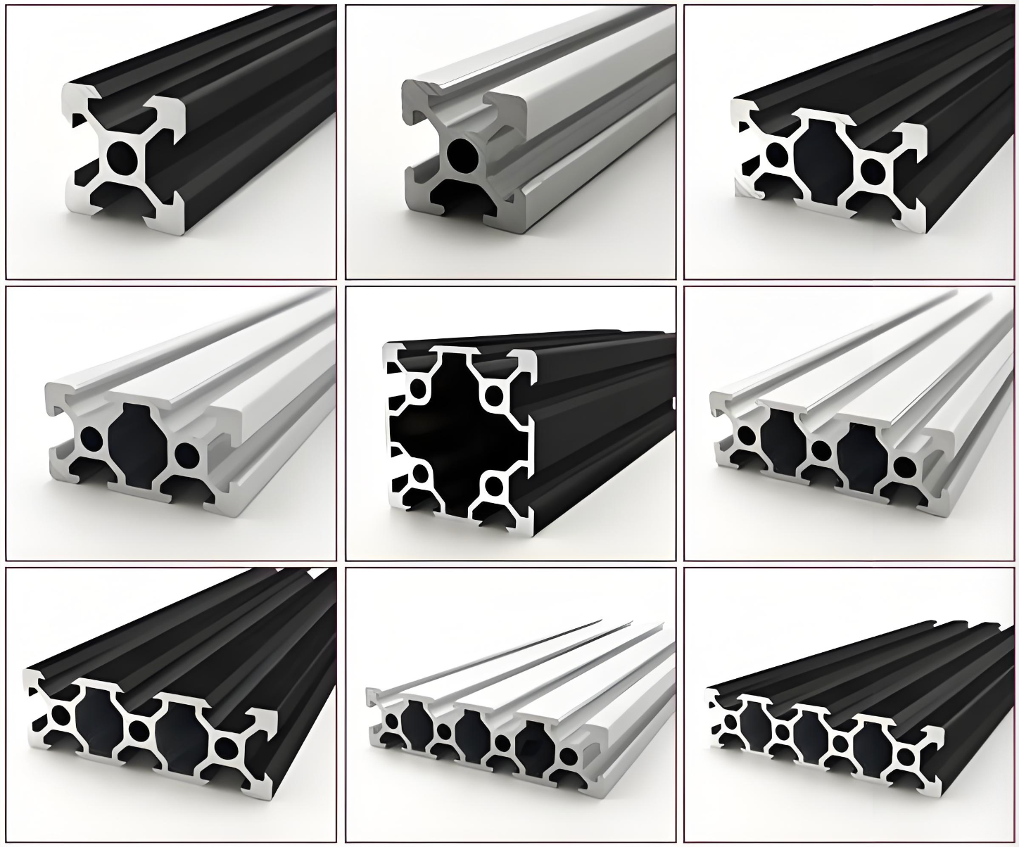
Custom T-Slot & V-Slot Aluminum Extrusions | Industrial Frame Profiles
T-slot and V-slot aluminum profiles, extruded to your frame drawings. Slot tolerance ±0.15 mm, straightness 0.5 mm/m. Cut, drilled, tapped,…
Details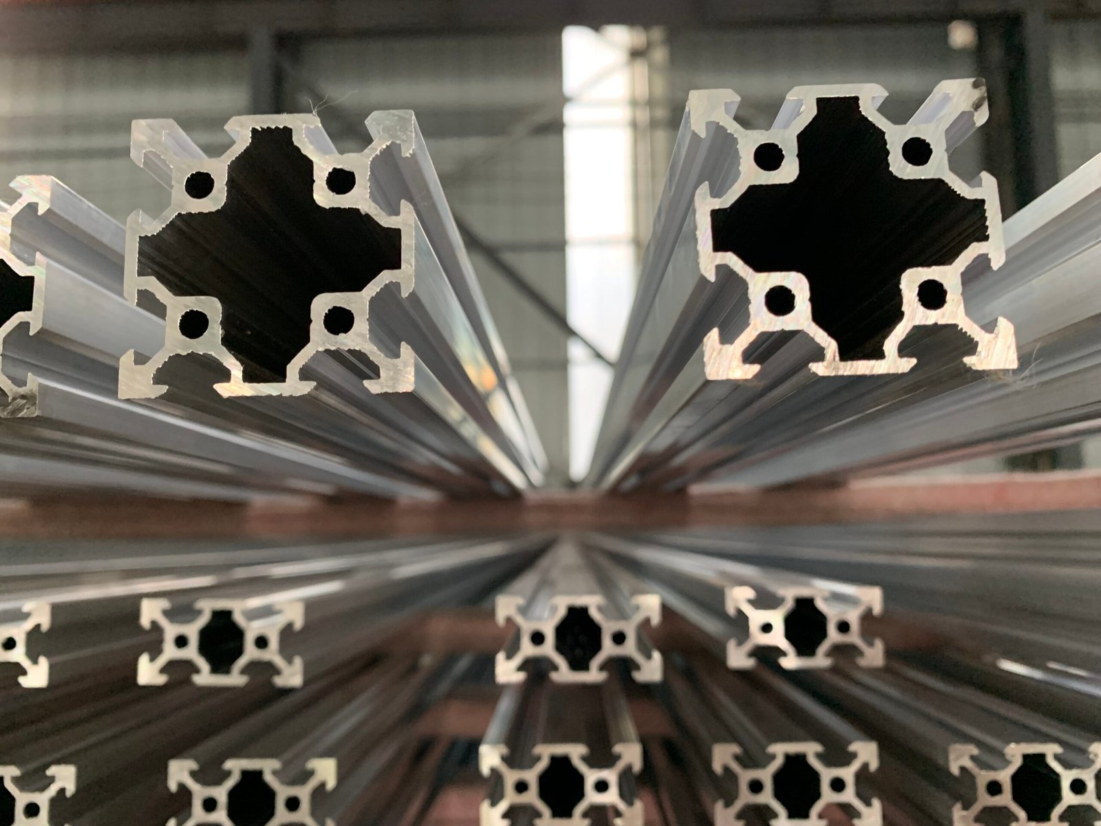
2020, 2040, 4040, 4080 Aluminum Extrusion Profiles | Frame Sizing & Load Guide
Don't guess the wrong size. 2020, 2040, 4040, and 4080 aluminum profiles explained with real span and load guidance. Cut,…
Details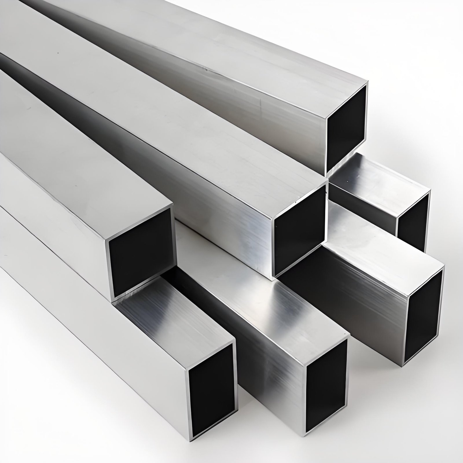
Aluminum Square & Rectangular Tube | Sizes, Load Guide, Cut-to-Length, Custom Extrusion
Aluminum square tube selection, load span chart, bending limits, and machining. Standard sizes and custom dies. 6063-T5, 6061-T6, 6005-T5. Pre-cut,…
Details